Nissan Maxima Service and Repair Manual: Vehicle speed signal circuit
Description
Combination meter sends vehicle speed signal to power steering control unit.
Diagnosis Procedure
1.PERFORM COMBINATION METER SELF-DIAGNOSIS
Perform combination meter self-diagnosis.
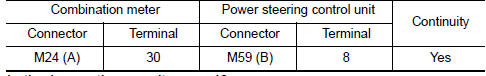
2.CHECK HARNESS BETWEEN COMBINATION METER AND POWER STEERING CONTROL UNIT FOR OPEN
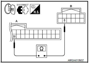
- Turn the ignition switch OFF.
- Disconnect combination meter connector.
- Disconnect power steering control unit connector.
- Check continuity between combination meter connector M24 (A)
terminal 30 and power steering control unit connector M59 (B)
terminal 8.
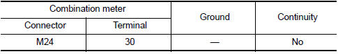
3.CHECK HARNESS BETWEEN COMBINATION METER AND POWER STEERING CONTROL UNIT FOR SHORT
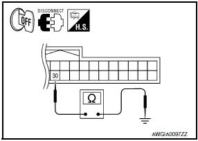
- Check continuity between combination meter connector M24
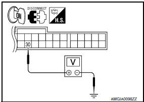
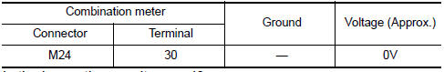
terminal 30 and ground. - Turn ignition switch ON.
- Check voltage between combination meter connector M24 terminal
30 and ground.
4.CHECK VEHICLE SPEED SIGNAL (COMBINATION METER SIDE)
- Turn the ignition switch OFF.
- Connect combination meter connector.
- Check combination meter input/output standard values.
5.CHECK VEHICLE SPEED SIGNAL (POWER STEERING CONTROL UNIT SIDE)
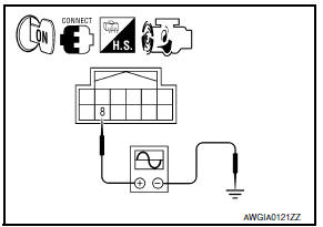
- Turn the ignition switch OFF.
- Connect power steering control unit connector.
- Start the engine.
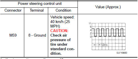
- Check signal between power steering control unit connector
M59 terminal 8 and ground with oscillosco
6.CHECK TERMINALS AND HARNESS CONNECTORS
- Check power steering control unit pin terminals for damage or loose connection with harness connector.
- Check combination meter pin terminals for damage or loose connection with harness connector.
 Engine speed signal circuit
Description
ECM sends engine speed signal to power steering control unit.
Diagnosis Procedure
1.PERFORM ECM SELF-DIAGNOSIS
With CONSULT
Perform ECM self-diagnosis.
2.CHECK HARNESS BETWEEN ECM AN ...
 ECU diagnosis information
POWER STEERING CONTROL UNIT
Reference Value
TERMINA LAYOUT
PHYSICAL VALUES
CAUTION: When using circuit tester or oscilloscope to
measure voltage for inspection, be sure not to extend forcibl ...
Other materials:
Diagnosis system (ipdm E/R)
Diagnosis Description
AUTO ACTIVE TEST
Description
In auto active test mode, the IPDM E/R sends a drive signal to the following
systems to check their operation.
Oil pressure warning lamp
Front wiper (LO, HI)
Parking lamps
Side marker lamps
License plate lamps
Tail lamps
Front f ...
Windshield-washer fluid
Windshield-washer fluid reservoir
Fill the windshield-washer fluid reservoir periodically.
Add windshield-washer fluid when the low
windshield-washer fluid warning light comes on.
To fill the windshield-washer fluid reservoir, lift
the cap off the reservoir and pour the windshieldwasher ...
Basic inspection
DIAGNOSIS AND REPAIR WORK FLOW
Work Flow
OVERALL SEQUENCE
DETAILED FLOW
1.GET INFORMATION FOR SYMPTOM
Get detailed information from the customer about the symptom (the condition
and the environment when the
incident/malfunction occurred).
2.CONFIRM THE SYMPTOM
Try to confirm the sympt ...
Nissan Maxima Owners Manual
- Illustrated table of contents
- Safety-Seats, seat belts and supplemental restraint system
- Instruments and controls
- Pre-driving checks and adjustments
- Monitor, climate, audio, phone and voice recognition systems
- Starting and driving
- In case of emergency
- Appearance and care
- Do-it-yourself
- Maintenance and schedules
- Technical and consumer information
Nissan Maxima Service and Repair Manual

0.0067