Nissan Maxima Service and Repair Manual: ECU diagnosis information
POWER STEERING CONTROL UNIT
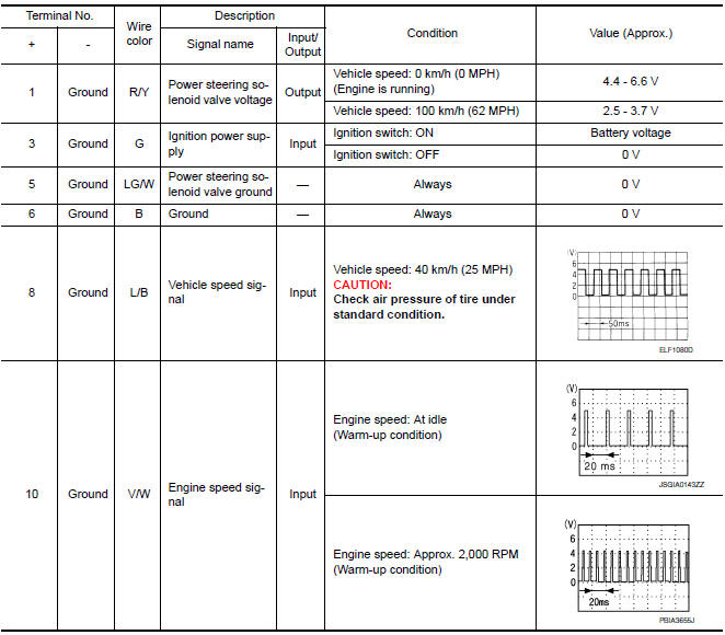
Reference Value
TERMINA LAYOUT

PHYSICAL VALUES
CAUTION: When using circuit tester or oscilloscope to measure voltage for inspection, be sure not to extend forcibly any connector terminals.
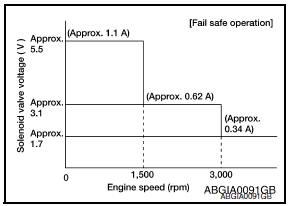
Fail Saf
EPS system
- EPS system enters the fail-safe mode (that allows the steering
force to be controlled without impairing the drive ability) if any of
the input/output signals to/from EPS system (power steering control
unit) deviate from the standard.
NOTE:
The system enters the fail-safe mode if the engine speed remains
at 1,500 RPM or more for over 10 seconds while the vehicle is
stopped. This is normal. - The fail-safe function is cancelled when a vehicle speed signal of 2
km/h (1.2 MPH) or more is inputted or the key switch is turned
OFF→ ON. EPS system restores the normal operation at that time
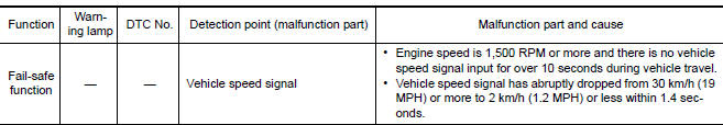
 Vehicle speed signal circuit
Description
Combination meter sends vehicle speed signal to power steering control unit.
Diagnosis Procedure
1.PERFORM COMBINATION METER SELF-DIAGNOSIS
Perform combination meter self-diagnosis.
2 ...
 Wiring diagram
ELECTRONICALLY CONTROLLED POWER STEERING SYSTEM
Wiring Diagram
...
Other materials:
Rear window defogger power supply and ground circuit
Description
Heats the heating wire with the power supply from the rear window defogger
relay to prevent the rear window
from fogging up.
Component Function Check
1. CHECK REAR WINDOW DEFOGGER
Check that the heating wire of rear window defogger is heated when turning
the rear window defogge ...
Warning lamp
Description
Warning lamp is built in combination meter.
Intelligent Key system malfunction is reported
to the driver by the warning lamp illumination.
Component Function Check
1.CHECK FUNCTION
Perform "INDICATOR" in the "Active Test" mode
with CON ...
Air fresheners
Most air fresheners use a solvent that could affect
the vehicle interior. If you use an air freshener,
take the following precautions:
Hanging-type air fresheners can cause permanent
discoloration when they contact vehicle
interior surfaces. Place the air freshener
in a location that all ...
Nissan Maxima Owners Manual
- Illustrated table of contents
- Safety-Seats, seat belts and supplemental restraint system
- Instruments and controls
- Pre-driving checks and adjustments
- Monitor, climate, audio, phone and voice recognition systems
- Starting and driving
- In case of emergency
- Appearance and care
- Do-it-yourself
- Maintenance and schedules
- Technical and consumer information
Nissan Maxima Service and Repair Manual

0.0052