Nissan Maxima Service and Repair Manual: Diagnosis system (meter)
Diagnosis Description
SELF-DIAGNOSIS MODE
- Odo/trip meter and information display segment operation can be checked in self-diagnosis mode.
- Meters/gauges can be checked in self-diagnosis mode.
OPERATION PROCEDURE
- Turn the ignition switch OFF.
- While pushing the odo/trip meter switch, turn the ignition switch ON again.
- Push the odo/trip meter switch at least 3 times within 7 seconds after the ignition switch is turned ON.
- The unified meter control unit is turned to self-diagnosis mode.
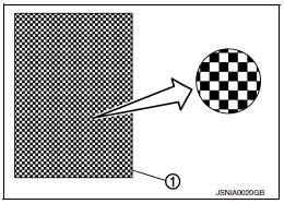
- All the segments on the odo/trip meter illuminate.
- Dots in all segments of information display LCD (1) flash alternately.
NOTE:
If any of the segments are not displayed, replace the combination meter. Refer to MWI-122, "Removal and Installation".
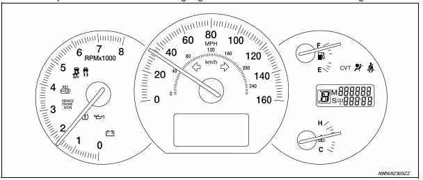
5. Push the odo/trip meter switch. Each meter/gauge should indicate as shown in the figure.
CONSULT Function (METER/M&A)
CONSULT can display each diagnostic item using the diagnostic test modes shown following.
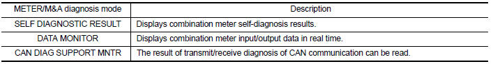
SELF-DIAG RESULTS
Display Item List
Refer to MWI-51, "DTC Index".
DATA MONITOR
Display Item List
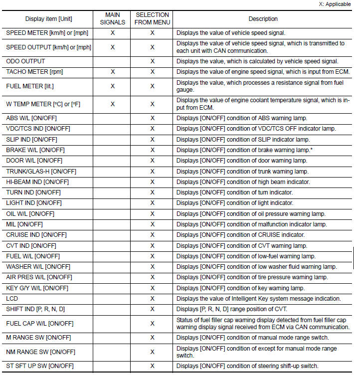
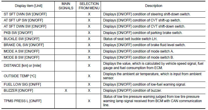
NOTE:
Some items are not available due to vehicle specification.
*: The monitor will indicate "OFF" even though the brake warning lamp is on if either of the following conditions exist.
- The parking brake is engaged
- The brake fluid level is low
 Warning chime system
WARNING CHIME SYSTEM : System Diagram
WARNING CHIME SYSTEM : System Description
COMBINATION METER
The buzzer (1) for warning chime system is installed in the
combination
meter.
The buz ...
 Diagnosis system (BCM)
BUZZER
BUZZER : CONSULT Function (BCM - BUZZER)
DATA MONITOR
ACTIVE TEST
...
Other materials:
Steering switch
Removal and Installation
REMOVAL
Remove the driver airbag module. Refer to SR-12, "Removal and
Installation".
Remove the steering wheel audio control switch screws (A).
Release the steering wheel audio control switch harness clips
(B).
Remove the steering wheel audio c ...
Servicing air conditioner
The air conditioner system in your NISSAN vehicle
is charged with a refrigerant designed with
the environment in mind.
This refrigerant does not harm the earth's
ozone layer.
Special charging equipment and lubricant is required
when servicing your NISSAN air conditioner.
Using improper refr ...
ECU diagnosis information
BCM (BODY CONTROL MODULE)
Reference Value
NOTE:
The Signal Tech II Tool (J-50190) can be used to perform the following
functions. Refer to the Signal Tech II
User Guide for additional information.
Activate and display TPMS transmitter IDs
Display tire pressure reported by the TPMS tran ...
Nissan Maxima Owners Manual
- Illustrated table of contents
- Safety-Seats, seat belts and supplemental restraint system
- Instruments and controls
- Pre-driving checks and adjustments
- Monitor, climate, audio, phone and voice recognition systems
- Starting and driving
- In case of emergency
- Appearance and care
- Do-it-yourself
- Maintenance and schedules
- Technical and consumer information
Nissan Maxima Service and Repair Manual

0.0054