Nissan Maxima Service and Repair Manual: Warning chime system
WARNING CHIME SYSTEM : System Diagram
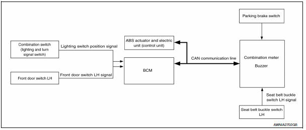
WARNING CHIME SYSTEM : System Description
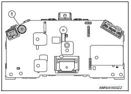
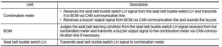
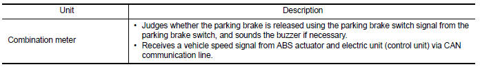
COMBINATION METER
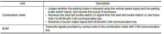
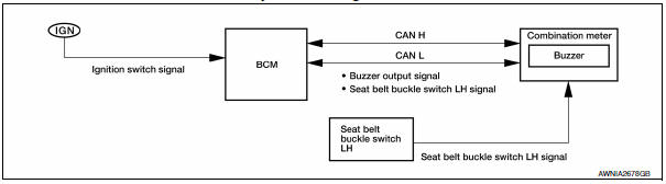
- The buzzer (1) for warning chime system is installed in the combination meter.
- The buzzer sounds when the combination meter receives a buzzer output signal from each unit.
BCM
BCM receives signals from various units and transmits a buzzer output signal to the combination meter with CAN communication line if it judges that the warning buzzer should be activated.
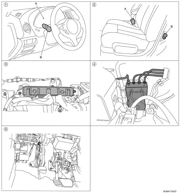
WARNING CHIME SYSTEM : Component Parts Location
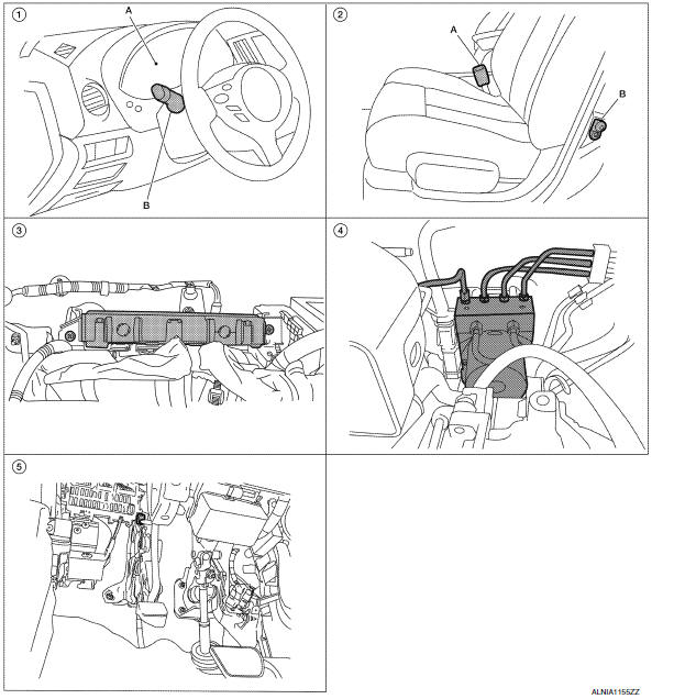
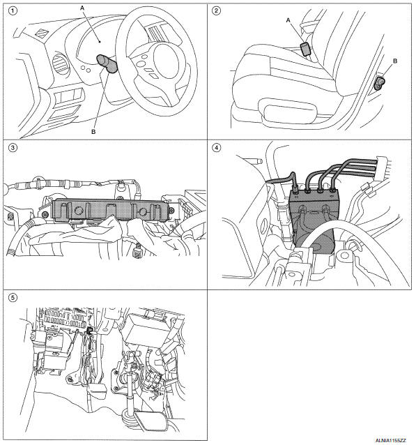
- A. Combination meter M24 B. Combination switch (lighting and turn signal switch) M28
- A. Seat belt buckle switch LH B202 B. Front door switch LH B8
- BCM M16, M17, M18, M19 (view with instrument panel removed)
- ABS actuator and electric unit (control unit) E26
- Parking brake switch E35 [view with instrument panel lower cover (LH) removed]
WARNING CHIME SYSTEM : Component Description
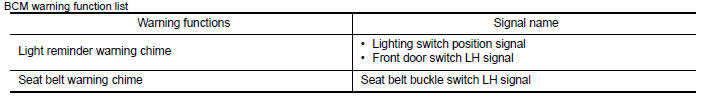
LIGHT REMINDER WARNING CHIME
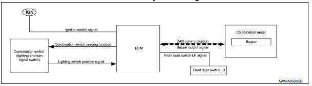
LIGHT REMINDER WARNING CHIME : System Diagram
LIGHT REMINDER WARNING CHIME : System Description
DESCRIPTION
With ignition switch in OFF or ACC position, driver door open, and lighting switch in 1ST or 2ND position, the light warning chime will sound.
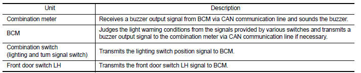
- BCM detects ignition switch in OFF or ACC position, front door switch LH ON, and lighting switch in 1ST or 2ND position and then transmits buzzer output signal (light reminder warning chime) to combination meter with CAN communication line.
- When combination meter receives buzzer output signal (light reminder warning chime), it sounds the buzzer.
WARNING OPERATION CONDITIONS
If all of the following conditions are fulfilled
- Lighting switch is at 1st or 2nd position
- Ignition switch is at OFF or ACC
- Front door switch LH is ON
WARNING CANCEL CONDITIONS
Warning is canceled if any of the following conditions is fulfilled.
- Lighting switch OFF
- Ignition switch ON
- Front door switch LH is OFF
LIGHT REMINDER WARNING CHIME : Component Parts Location

- A. Combination meter M24 B. Combination switch (lighting and turn signal switch) M28
- A. Seat belt buckle switch LH B202 B. Front door switch LH B8
- BCM M16, M17, M18, M19 (view with instrument panel removed)
- ABS actuator and electric unit (control unit) E26
- Parking brake switch E35 [view with instrument panel lower cover (LH) removed]
LIGHT REMINDER WARNING CHIME : Component Description
SEAT BELT WARNING CHIME
SEAT BELT WARNING CHIME : System Diagram
SEAT BELT WARNING CHIME : System Description
DESCRIPTION
With ignition switch turned ON and driver seat belt unfastened, seat belt warning chime will sound for approximately 6 seconds.
- BCM receives seat belt buckle switch LH signal from combination meter with CAN communication line.
- BCM detects ignition switch turned ON and seat belt buckle switch LH ON and then transmits buzzer output signal (seat belt warning chime) to combination meter with CAN communication line.
- When combination meter receives buzzer output signal (seat belt warning chime), it sounds the buzzer.
WARNING OPERATION CONDITIONS
If all of the following conditions are fulfilled
- Ignition switch OFF→ON
- Seat buckle switch LH is ON (driver seat belt not fastened)
WARNING CANCEL CONDITIONS
Cancels the warning if any of the following conditions is fulfilled.
- Ignition switch OFF
- Seat buckle switch LH is OFF (driver seat belt fastened)
- 90 seconds have passed since the start of the warning
SEAT BELT WARNING CHIME : Component Parts Location
- A. Combination meter M24 B. Combination switch (lighting and turn signal switch) M28
- A. Seat belt buckle switch LH B202 B. Front door switch LH B8
- BCM M16, M17, M18, M19 (view with instrument panel removed)
- ABS actuator and electric unit (control unit) E26
- Parking brake switch E35 [view with instrument panel lower cover (LH) removed]
SEAT BELT WARNING CHIME : Component Description
PARKING BRAKE RELEASE WARNING CHIME
PARKING BRAKE RELEASE WARNING CHIME : System Diagram
PARKING BRAKE RELEASE WARNING CHIME : System Description
DESCRIPTION
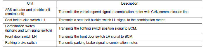
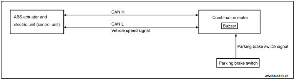
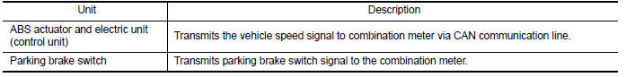
- The combination meter receives the vehicle speed signal from the ABS actuator and electric unit (control unit) via CAN communication line.
- The combination meter judges whether the parking brake is released using the parking brake switch signal from the parking brake switch, and sounds the warning buzzer if necessary.
WARNING OPERATION CONDITIONS
If all of the following conditions are fulfilled
- Vehicle speed is approximately 7 km/h (4.3 MPH) or higher
- Parking brake switch ON
WARNING CANCEL CONDITIONS
Warning is canceled if any of the following conditions is fulfilled.
- Vehicle speed is approximately 3 km/h (1.9 MPH) or less
- Parking brake switch OFF
PARKING BRAKE RELEASE WARNING CHIME : Component Parts Location
- A. Combination meter M24 B. Combination switch (lighting and turn signal switch) M28
- A. Seat belt buckle switch LH B202 B. Front door switch LH B8
- BCM M16, M17, M18, M19 (view with instrument panel removed)
- ABS actuator and electric unit (control unit) E26
- Parking brake switch E35 [view with instrument panel lower cover (LH) removed]
PARKING BRAKE RELEASE WARNING CHIME : Component Description

 Diagnosis system (meter)
Diagnosis Description
SELF-DIAGNOSIS MODE
Odo/trip meter and information display segment operation can be
checked in self-diagnosis mode.
Meters/gauges can be checked in self-diagnosis mode. ...
Other materials:
Rear disc brake
BRAKE PAD
BRAKE PAD : Inspection of Pad
PAD WEAR
Check pad thickness from the inspection hole on cylinder body.
Check using a scale if necessary
DISC ROTOR
DISC ROTOR : Inspection of Rotor
VISUAL
Check surface of disc rotor for uneven wear, cracks, and serious damage.
Replace if ne ...
Basic inspection
DIAGNOSIS AND REPAIR WORKFLOW
Work Flow
OVERALL SEQUENCE
DETAILED FLOW
1. GET INFORMATION FOR SYMPTOM
Get the detailed information from the customer about the symptom (the
condition and the environment when
the incident/malfunction occurred).
2. CHECK DTC
Check DTC for BCM and IPDM ...
B2562 Low voltage
DTC Logic
DTC DETECTION LOGIC
DTC CONFIRMATION PROCEDURE
1. DTC CONFIRMATION
Erase DTC.
Turn ignition switch OFF.
Perform the "SELF-DIAG RESULTS" of BCM with CONSULT, after the
ignition switch has been turned ON
for 1.5 seconds or more.
Diagnosis Procedure
1. CHECK ...
Nissan Maxima Owners Manual
- Illustrated table of contents
- Safety-Seats, seat belts and supplemental restraint system
- Instruments and controls
- Pre-driving checks and adjustments
- Monitor, climate, audio, phone and voice recognition systems
- Starting and driving
- In case of emergency
- Appearance and care
- Do-it-yourself
- Maintenance and schedules
- Technical and consumer information
Nissan Maxima Service and Repair Manual

0.0055