Nissan Maxima Service and Repair Manual: Diagnosis and repair workflow
Work Flow
PRECAUTIONS FOR DIAGNOSIS
If steering angle sensor, steering system parts, suspension system parts, ABS actuator and electric unit (control unit) or if wheel alignment has been adjusted, be sure to adjust neutral position of steering angle sensor before driving. Refer to BRC-6, "ADJUSTMENT OF STEERING ANGLE SENSOR NEUTRAL POSITION : Description".
OVERALL SEQUENCE
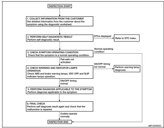
1.COLLECT INFORMATION FROM THE CUSTOMER
Get detailed information from the customer about the symptom (the condition and the environment when the incident/malfunction occurred) using the diagnosis worksheet.
2.PERFORM SELF DIAGNOSTIC RESULT
Perform self diagnostic result
3.CHECK SYMPTOM OPERATING CONDITION
Check that the symptom is a normal operating condition
4.CHECK WARNING AND INDICATOR LAMPS OPERATION
Check warning and indicator lamps operation.
- ABS warning lamp:
- Brake warning lamp:
- VDC OFF indicator lamp
- SLIP indicator lamp:
5.PERFORM DIAGNOSIS APPLICABLE TO THE SYMPTOM
Perform diagnosis applicable to the symptom.
6.FINAL CHECK
Perform self diagnostic result again, and check that the malfunction is repaired. After checking, erase the self diagnosis memory
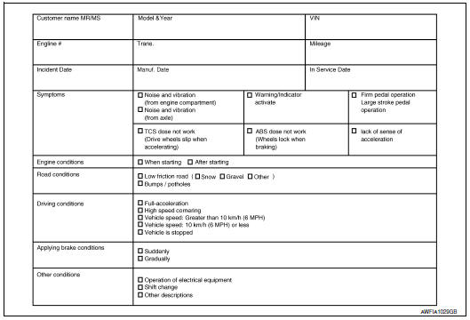
Diagnostic Work Sheet
 Basic inspection
...
 Inspection and adjustment
ADDITIONAL SERVICE WHEN REPLACING CONTROL UNIT
ADDITIONAL SERVICE WHEN REPLACING CONTROL UNIT : Description
After replacing the ABS actuator and electric unit (control unit), perform
the neutral p ...
Other materials:
Precautions in repairing high strength steel
High Strength Steel (HSS)
High strength steel is used for body panels in order to reduce vehicle
weight.
Accordingly, precautions in repairing automotive bodies made of high strength
steel are described below:
Read the following precautions when repairing HSS:
Additional points to c ...
Precaution
Precaution for Supplemental Restraint System (SRS) "AIR BAG" and
"SEAT BELT PRE-TENSIONER"
The Supplemental Restraint System such as "AIR BAG" and "SEAT BELT
PRE-TENSIONER", used along with a front seat belt, helps to reduce the risk
or severity of injury to the driver and front passenger for ...
ADP branch line circuit
Diagnosis Procedure
1.CHECK CONNECTOR
Turn the ignition switch OFF.
Disconnect the battery cable from the negative terminal.
Check the following terminals and connectors for damage, bend and
loose connection (unit side and connector
side).
Driver seat control unit
Harness connec ...
Nissan Maxima Owners Manual
- Illustrated table of contents
- Safety-Seats, seat belts and supplemental restraint system
- Instruments and controls
- Pre-driving checks and adjustments
- Monitor, climate, audio, phone and voice recognition systems
- Starting and driving
- In case of emergency
- Appearance and care
- Do-it-yourself
- Maintenance and schedules
- Technical and consumer information
Nissan Maxima Service and Repair Manual

0.0055