Nissan Maxima Service and Repair Manual: Subwoofer
Description
The AV control unit sends audio signals to the BOSE speaker amp. The BOSE speaker amp. amplifies the audio signals before sending them to the subwoofers using the audio signal circuits.
Diagnosis Procedure
1.CONNECTOR CHECK
Check the AV control unit, BOSE speaker amp. and subwoofer connectors for the following:
- Proper connection
- Damage
- Disconnected or loose terminals
2.HARNESS CHECK
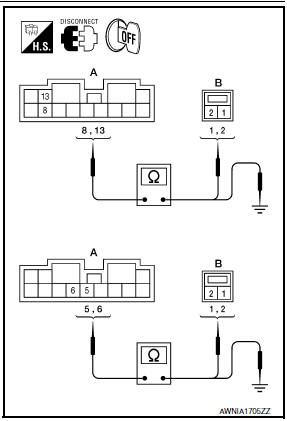
- Disconnect BOSE speaker amp. connector B110 and suspect rear subwoofer connector.
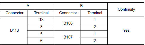
- Check continuity between BOSE speaker amp. harness connector B110 (A) and suspect rear subwoofer harness connector (B).
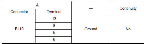
- Check continuity between BOSE speaker amp. harness connector B110 (A) and ground.
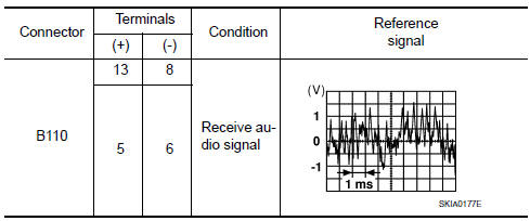
3.REAR SUBWOOFER SIGNAL CHECK
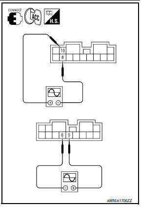
- Connect BOSE speaker amp. connector B110 and suspect rear subwoofer connector.
- Turn ignition switch to ACC.
- Push POWER switch.
- Check the signal between BOSE speaker amp. harness connector B110 terminals with CONSULT or oscilloscope.
4.HARNESS CHECK
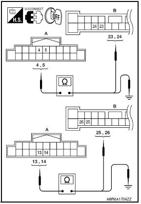
- Disconnect AV control unit connector M160 and BOSE speaker amp. connector B109.
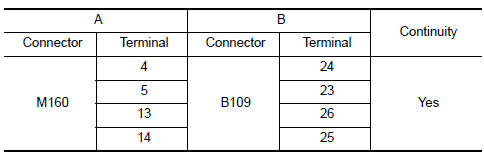
- Check continuity between AV control unit harness connector M160 (A) and BOSE speaker amp. harness connector B109 (B).
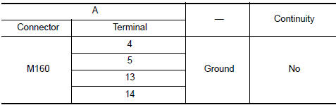
- Check continuity between AV control unit harness connector M160 (A) terminal and ground.
5.REAR SUBWOOFER SIGNAL CHECK
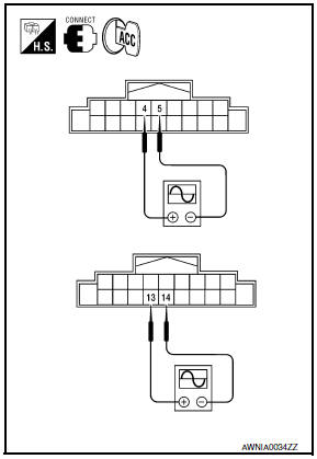
- Connect AV control unit connector M160 and BOSE speaker amp. connector B109.
- Turn ignition switch to ACC.
- Push POWER switch.
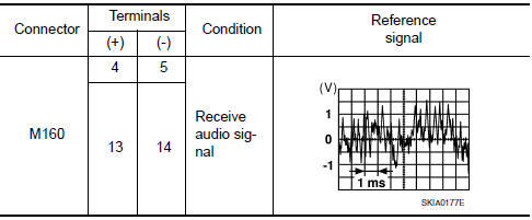
- Check the signal between AV control unit harness connector terminals with CONSULT or oscilloscope.
 Rear door speaker
Description
The AV control unit sends audio signals to the BOSE speaker amp. The BOSE
speaker amp. amplifies the
audio signals before sending them to the rear door speakers using the audio
sign ...
 Steering switch
Description
When one of the steering wheel audio control switches is pushed, the
resistance in the steering wheel audio
control switch circuit changes, depending on which button is pushed.
Diagn ...
Other materials:
MOD system limitations
WARNING
Listed below are the system limitations for
MOD. Failure to operate the vehicle in
accordance with these system limitations
could result in serious injury or death.
Do not use the MOD system when towing
a trailer. The system may not function
properly.
Excessive noise (for examp ...
Intelligent key system/engine start function symptoms
Symptom Table
Engine cannot be started with all Intelligent Keys.
CAUTION:
Follow Trouble Diagnosis Flowchart
referring to "SEC-4, "Work Flow"". Determine malfunctioning
condition before performing this diagnosis.
Check that vehicle is under the
condition shown in "Conditio ...
E-call (SOS) switch (if so equipped)
The E-call (SOS) system switch is used in combination
with a NissanConnectSM Services subscription
to call for assistance in case of an
emergency.
Pushing the switch will (with a paid subscription)
reach a Response Specialist that will provide
assistance based on the situation described ...
Nissan Maxima Owners Manual
- Illustrated table of contents
- Safety-Seats, seat belts and supplemental restraint system
- Instruments and controls
- Pre-driving checks and adjustments
- Monitor, climate, audio, phone and voice recognition systems
- Starting and driving
- In case of emergency
- Appearance and care
- Do-it-yourself
- Maintenance and schedules
- Technical and consumer information
Nissan Maxima Service and Repair Manual

0.0097