Nissan Maxima Service and Repair Manual: Steering switch
Description
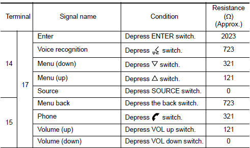
When one of the steering wheel audio control switches is pushed, the resistance in the steering wheel audio control switch circuit changes, depending on which button is pushed.
Diagnosis Procedure
1.CHECK STEERING WHEEL AUDIO CONTROL SWITCH RESISTANCE
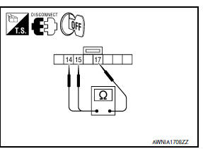
- Turn ignition switch OFF.
- Disconnect steering wheel audio control switch connector M88.
- Check resistance between steering switch connector terminals.
2.CHECK HARNESS BETWEEN COMBINATION SWITCH (SPIRAL CABLE) AND AV CONTROL UNIT
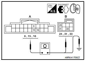
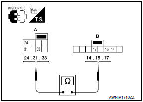
- Disconnect AV control unit connector M160 and combination switch (spiral cable) connector M30.
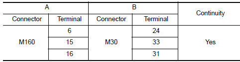
- Check continuity between AV control unit harness connector M160 (A) and combination switch (spiral cable) harness connector M30 (B).
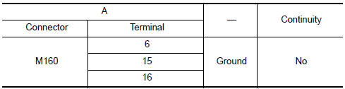
- Check continuity between AV switch connector M160 (A) and ground
3.COMBINATION SWITCH (SPIRAL CABLE) CHECK
- Disconnect combination switch (spiral cable) connector M88.
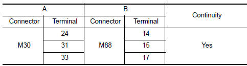
- Check continuity between combination switch (spiral cable) harness connector M30 (A) and M88 (B).
 Subwoofer
Description
The AV control unit sends audio signals to the BOSE speaker amp. The BOSE
speaker amp. amplifies the
audio signals before sending them to the subwoofers using the audio signal
circu ...

Other materials:
C1143, C1144 steering angle sensor
Description
The steering angle sensor detects the rotation amount, angular velocity and
direction of the steering wheel,
and transmits the data to the ABS actuator and electric unit (control unit) via
CAN communication.
DTC Logic
DTC DETECTION LOGIC
DTC CONFIRMATION PROCEDURE
1.CHECK ...
U121D AV control unit
DTC Logic
Diagnosis Pro
1.CHECK PLAYBACK OF A DISK (CD)
U121E AV CONTROL UNIT
DTC Logic
Diagnosis Procedure
1.CHECK PLAYBACK OF A DISK (CD)
U1225 AV CONTROL UNIT
DTC Logic
DTC DETECTION LOGIC
...
Diagnosis system (HVAC)
CONSULT Function
CONSULT can display each diagnosis item using the diagnosis test modes as
shown.
CONSULT application items
SELF DIAGNOSTIC RESULT
Display Item List
*: Perform self-diagnosis under sunshine. When performing indoors, aim a
light (more than 60 W) at sunload sensor, ...
Nissan Maxima Owners Manual
- Illustrated table of contents
- Safety-Seats, seat belts and supplemental restraint system
- Instruments and controls
- Pre-driving checks and adjustments
- Monitor, climate, audio, phone and voice recognition systems
- Starting and driving
- In case of emergency
- Appearance and care
- Do-it-yourself
- Maintenance and schedules
- Technical and consumer information
Nissan Maxima Service and Repair Manual

0.009