Nissan Maxima Service and Repair Manual: Wiring diagram
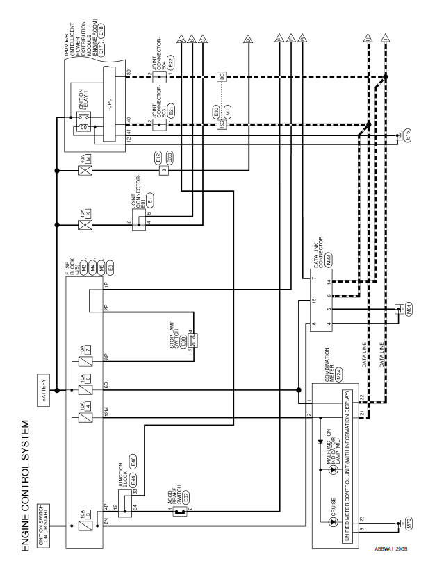
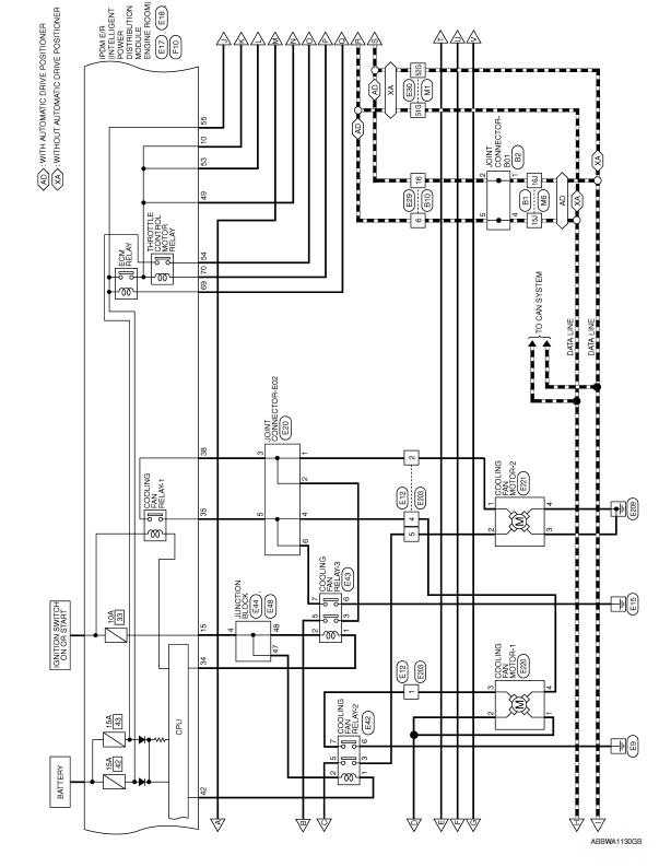
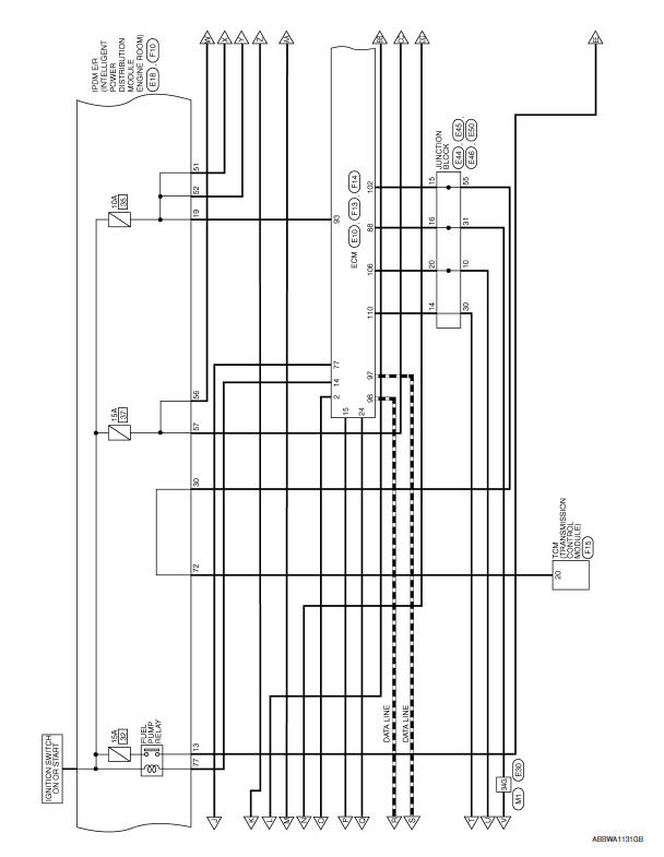
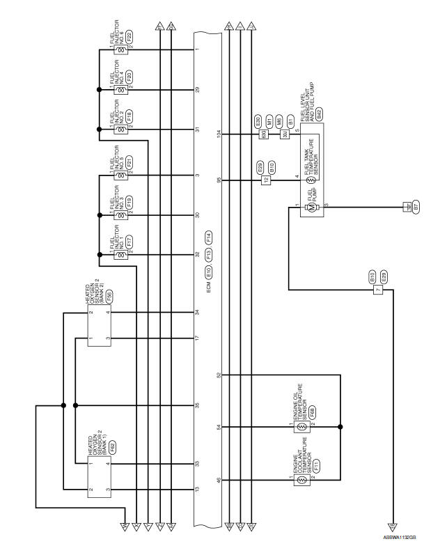
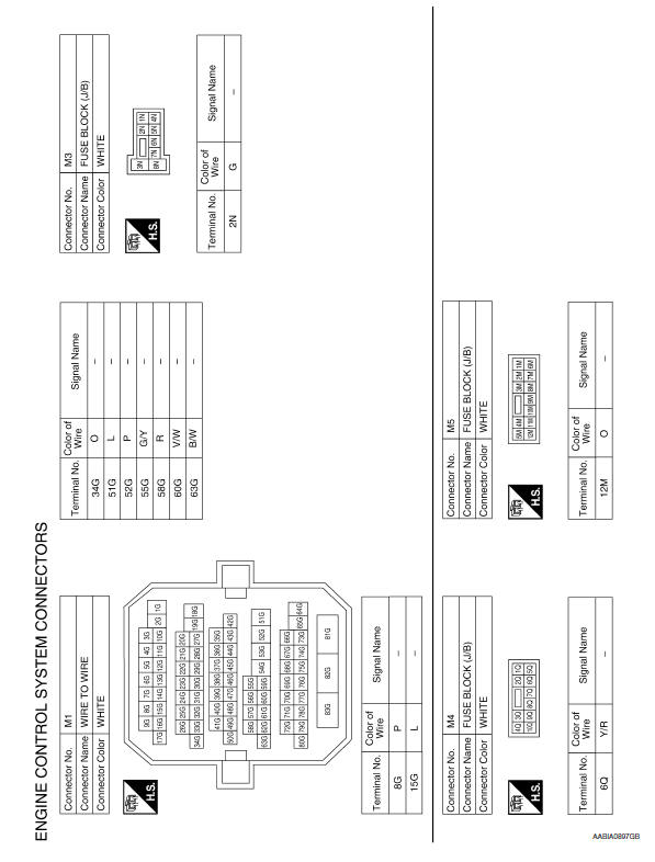
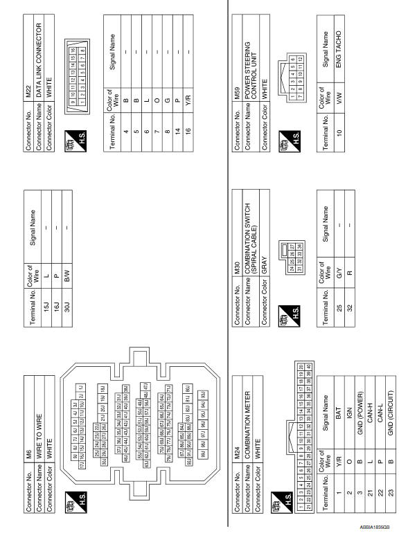
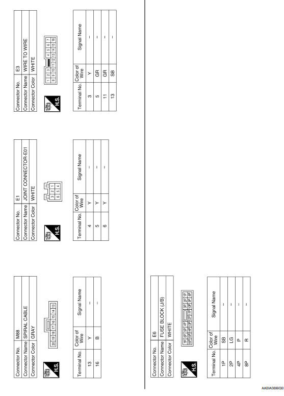
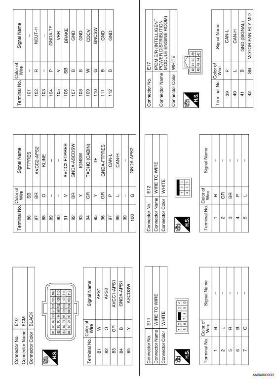
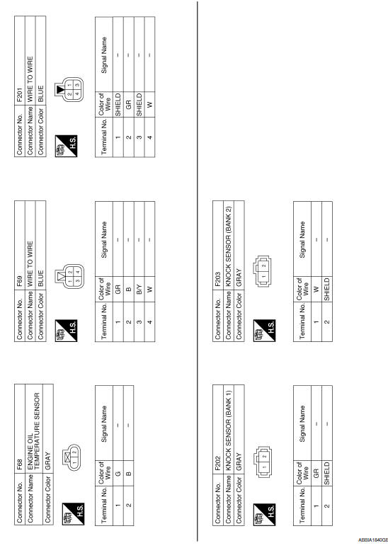
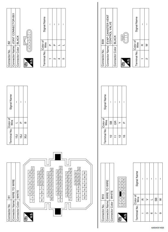
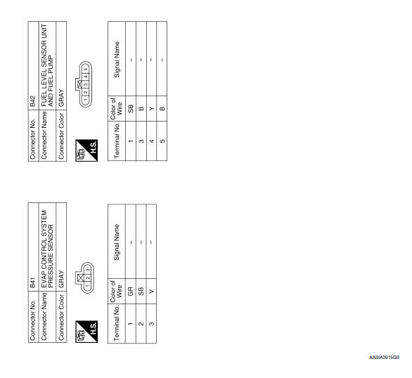
ENGINE CONTROL SYSTEM
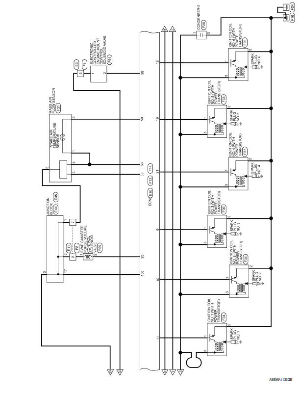
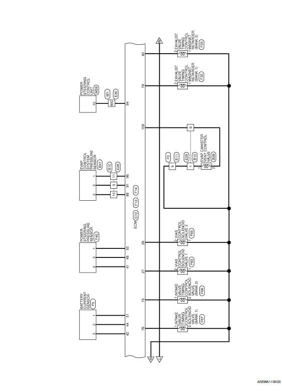
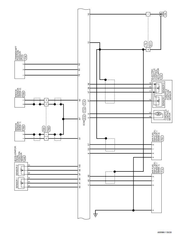
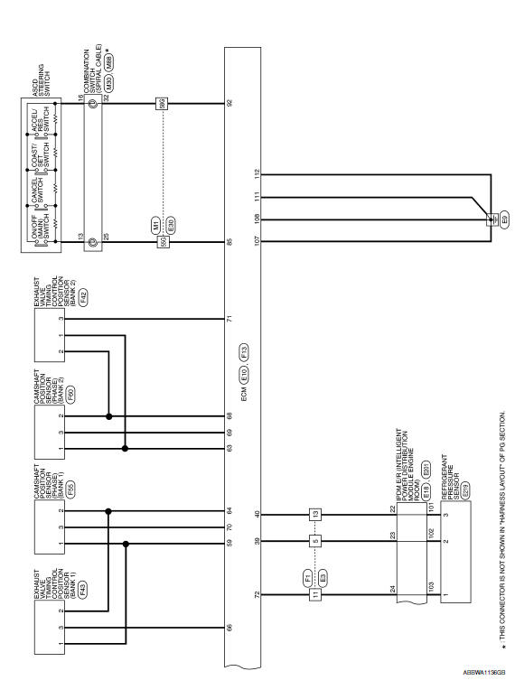
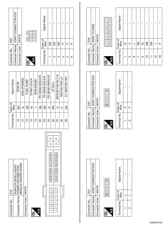
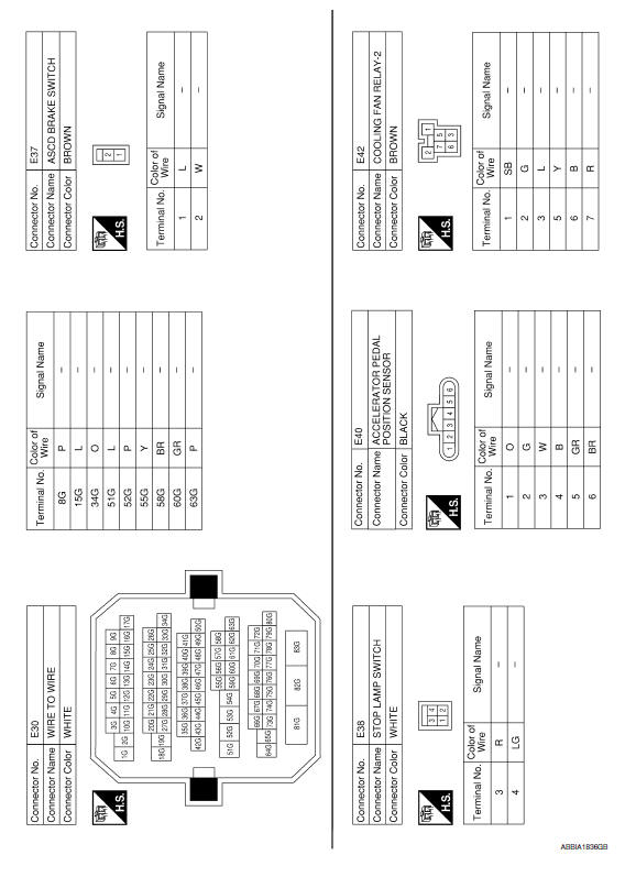
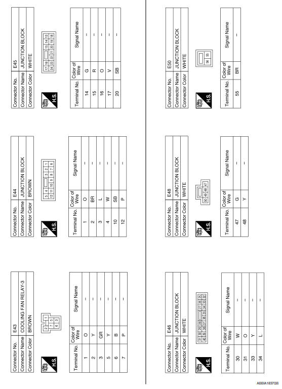
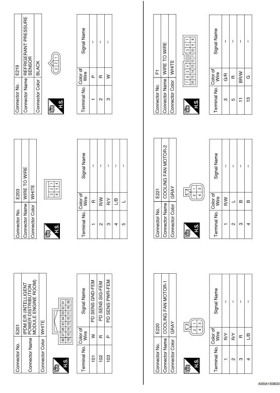
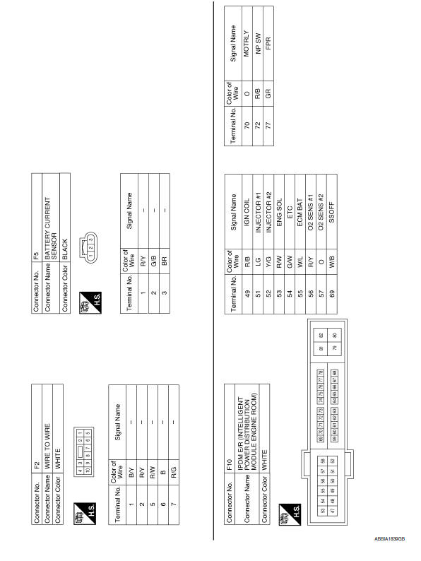
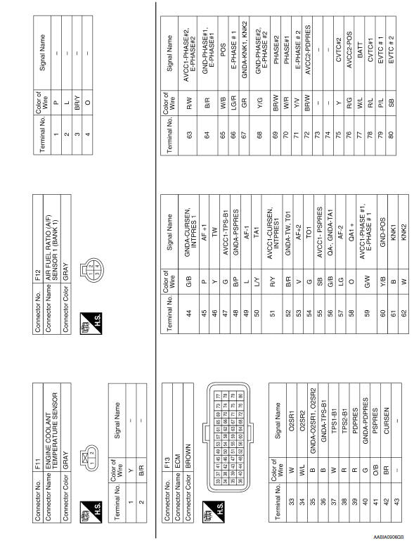
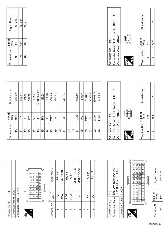
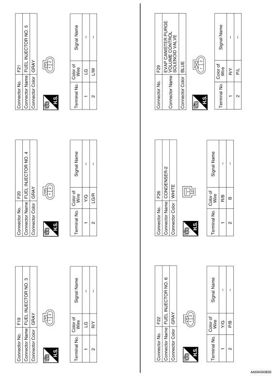
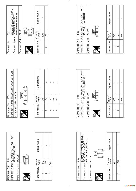
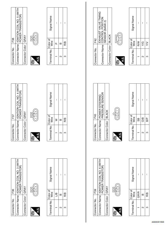
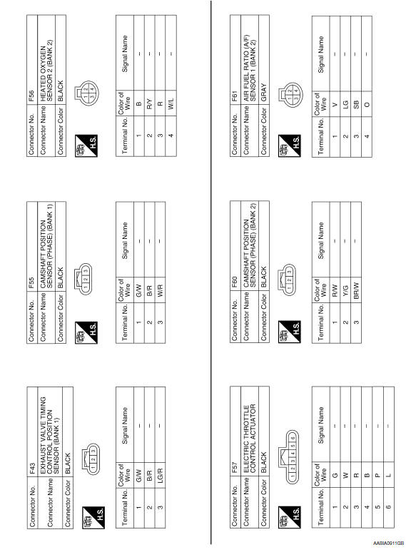
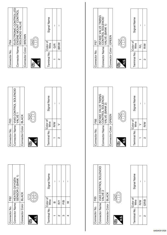
Wiring Diagram
 ECU diagnosis information
ECM
Reference Value
VALUES ON THE DIAGNOSIS TOOL
NOTE:
The following table includes information (items) inapplicable
to this vehicle. For information (items) applicable
to this vehi ...

Other materials:
Rear power window switch
Description
BCM supplies power.
Rear power window motor operates when rear power window switch is
activated.
Component Function Check
Rear Power Window Switch
1. CHECK REAR POWER WINDOW MOTOR FUNCTION
Check that rear power window motor operates from rear power window switch.
Diagnosi ...
Roof link assembly
Removal and Installation
Removal
Remove the sunshade. Refer to RF-153, "Removal and Installation".
Remove the wind deflector. Refer to RF-168, "Removal and Installation".
Remove the glass lid assembly. Refer to RF-150, "Removal and
Installation".
Remove the sunroof motor. Refer to RF-1 ...
Clearing the programmed information
The following procedure clears the programmed
information from both buttons. Individual buttons
cannot be cleared. However, individual buttons
can be reprogrammed. For additional information,
refer to "Reprogramming a single
HomeLink button" in this section.
To clear all programming:
1. Press ...
Nissan Maxima Owners Manual
- Illustrated table of contents
- Safety-Seats, seat belts and supplemental restraint system
- Instruments and controls
- Pre-driving checks and adjustments
- Monitor, climate, audio, phone and voice recognition systems
- Starting and driving
- In case of emergency
- Appearance and care
- Do-it-yourself
- Maintenance and schedules
- Technical and consumer information
Nissan Maxima Service and Repair Manual

0.006