Nissan Maxima Service and Repair Manual: ECU diagnosis information
ECM
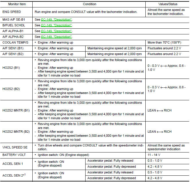
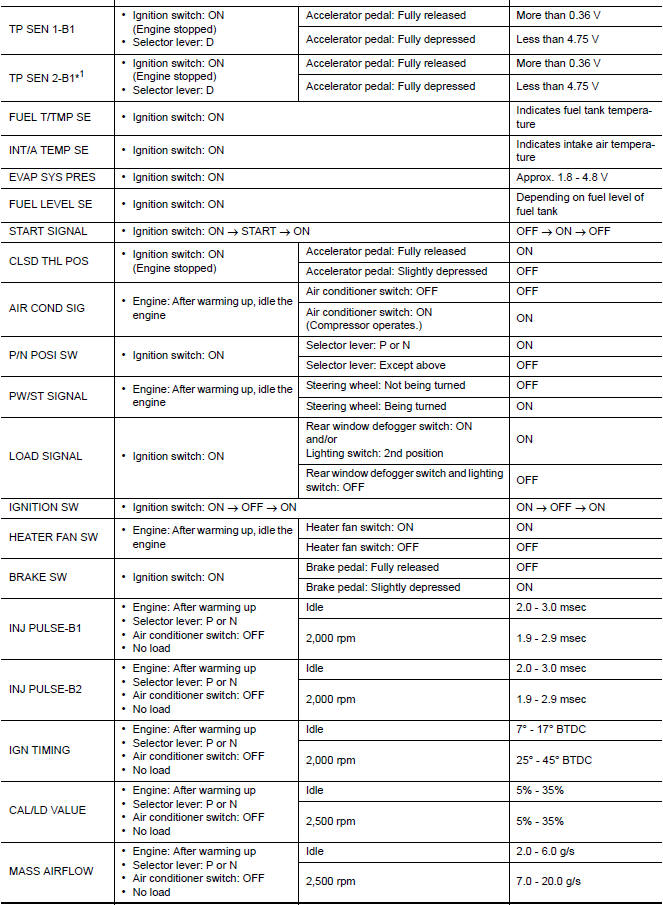
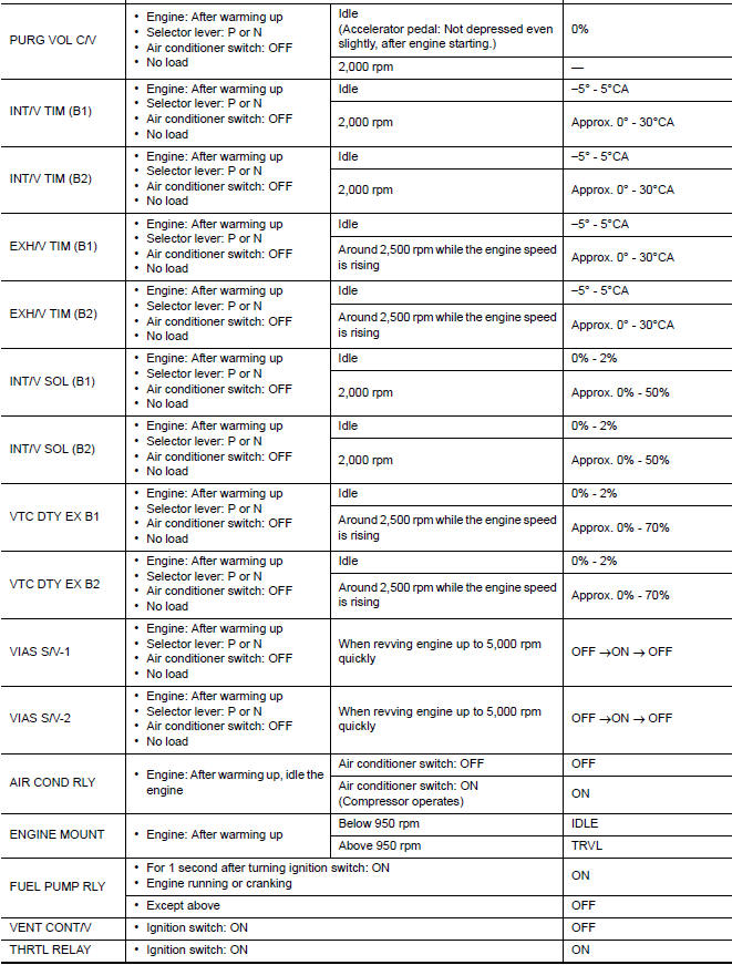
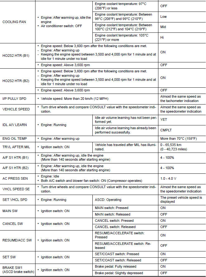
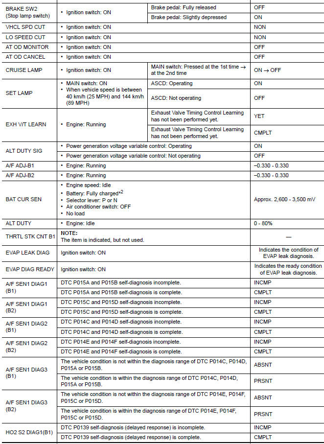
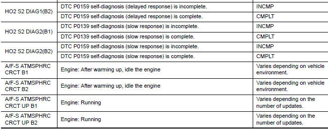
Reference Value
VALUES ON THE DIAGNOSIS TOOL
NOTE:
- The following table includes information (items) inapplicable to this vehicle. For information (items) applicable to this vehicle, refer to CONSULT display items.
- Numerical values in the following table are reference values.
- These values are input/output values that ECM receives/transmits and may differ from actual operations.
Example: The ignition timing shown by the timing light may differ from the ignition timing displayed on the data monitor. This occurs because the timing light shows a value calculated by ECM according to signals received from the cam shaft position sensor and other sensors related to ignition timing.
For outlines of following items, refer to EC-138, "CONSULT Function".
*1: Accelerator pedal position sensor 2 signal and throttle position sensor 2
signal are converted by ECM internally. Thus, they differ
from ECM terminals voltage signal.
*2: Before measuring the terminal voltage, confirm that the battery is fully
charged.
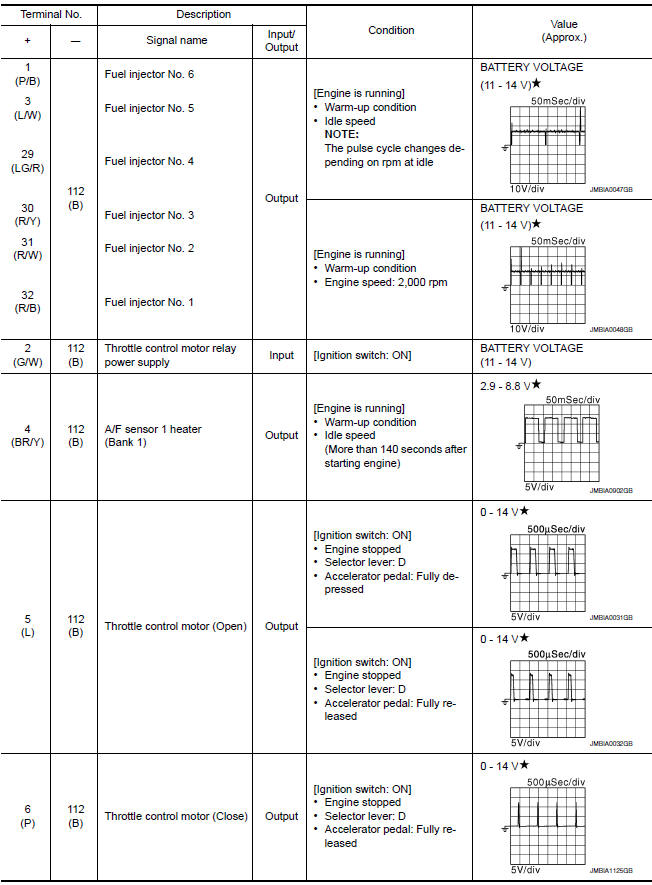
TERMINAL LAYOUT
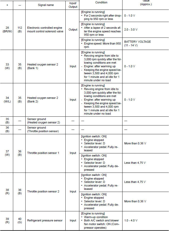
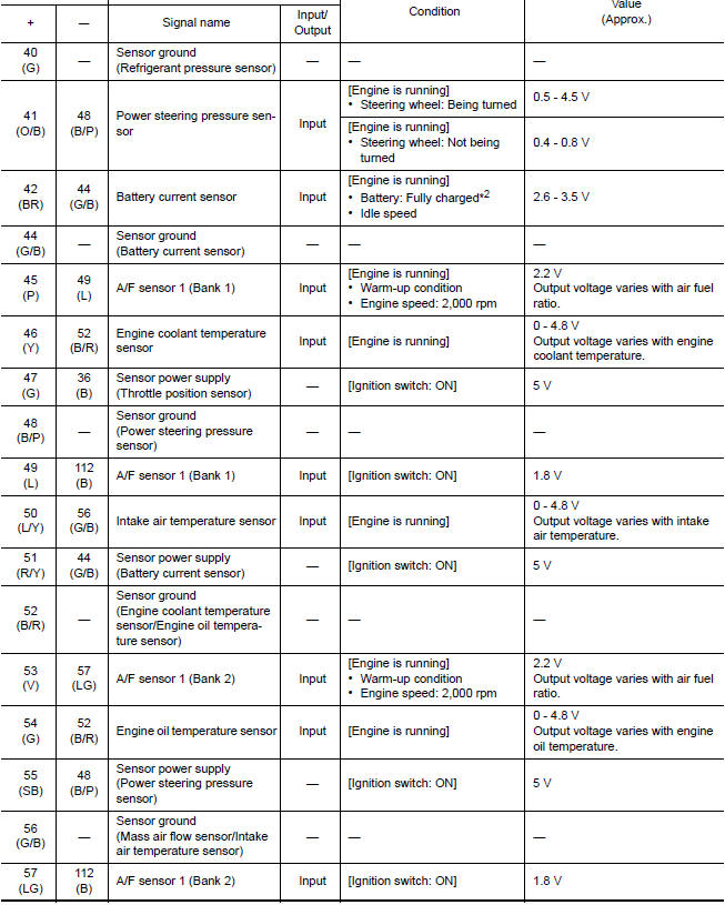
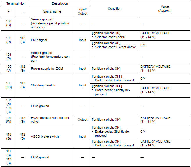
PHYSICAL VALUES
NOTE:
- ECM is located in the engine room left side near battery. For this inspection, remove passenger side instrument lower panel.
- Specification data are reference values.
- Pulse signal is measured by CONSULT.
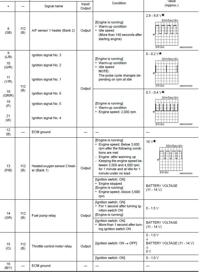
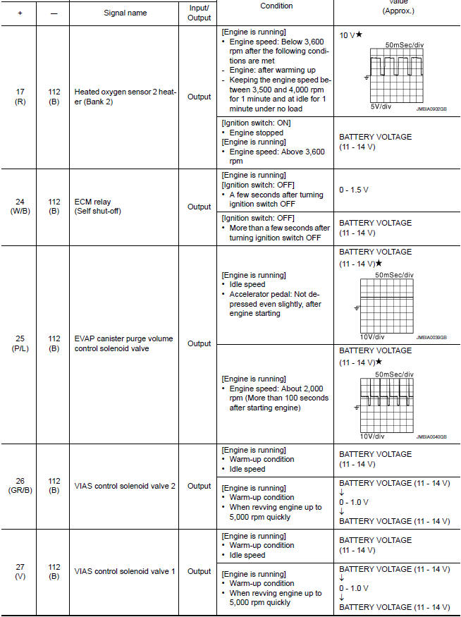
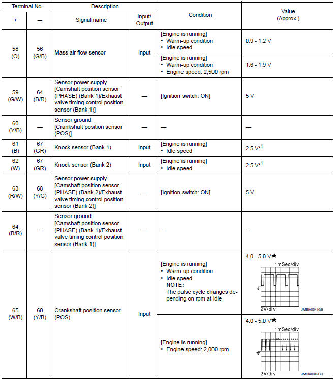
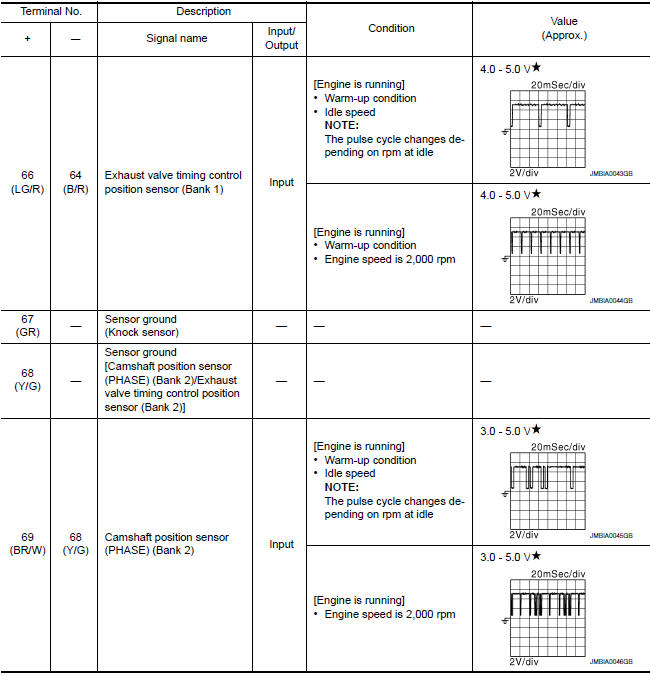
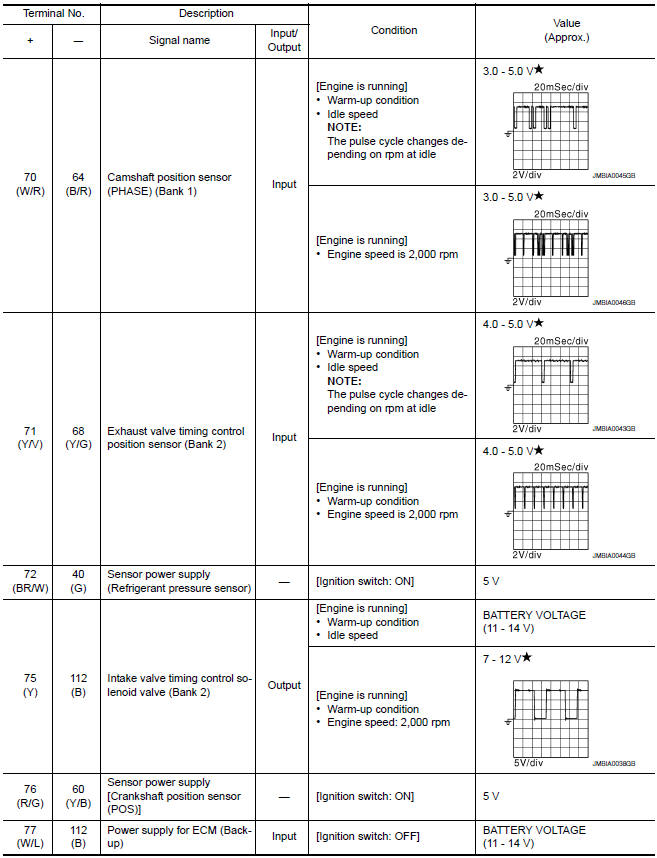
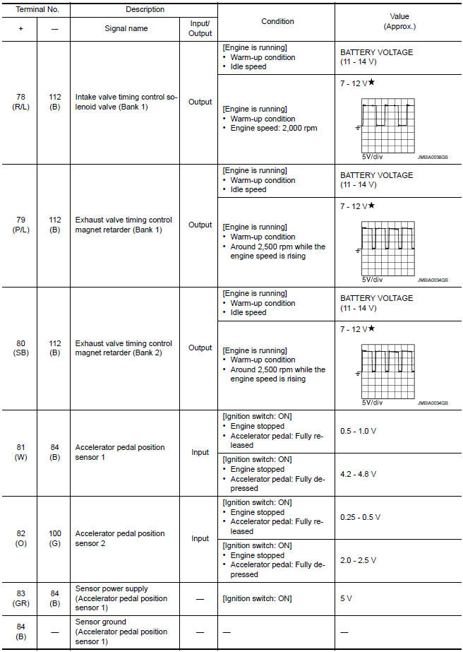
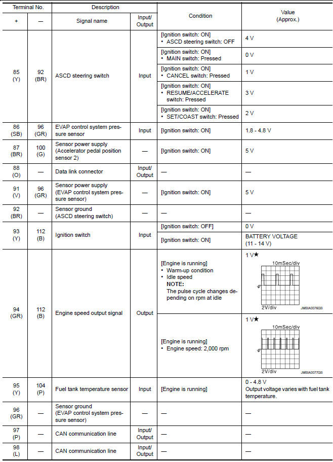
 : Average voltage for pulse
signal (Actual pulse signal can be confirmed by oscilloscope.)
: Average voltage for pulse
signal (Actual pulse signal can be confirmed by oscilloscope.)
*1: This may vary depending on internal resistance of the tester.
*2: Before measuring the terminal voltage, confirm that the battery is fully
charged.
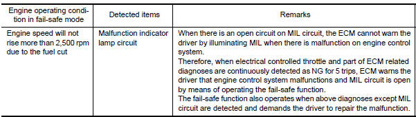
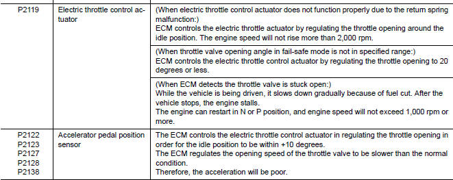
Fail safe
NON DTC RELATED ITEM
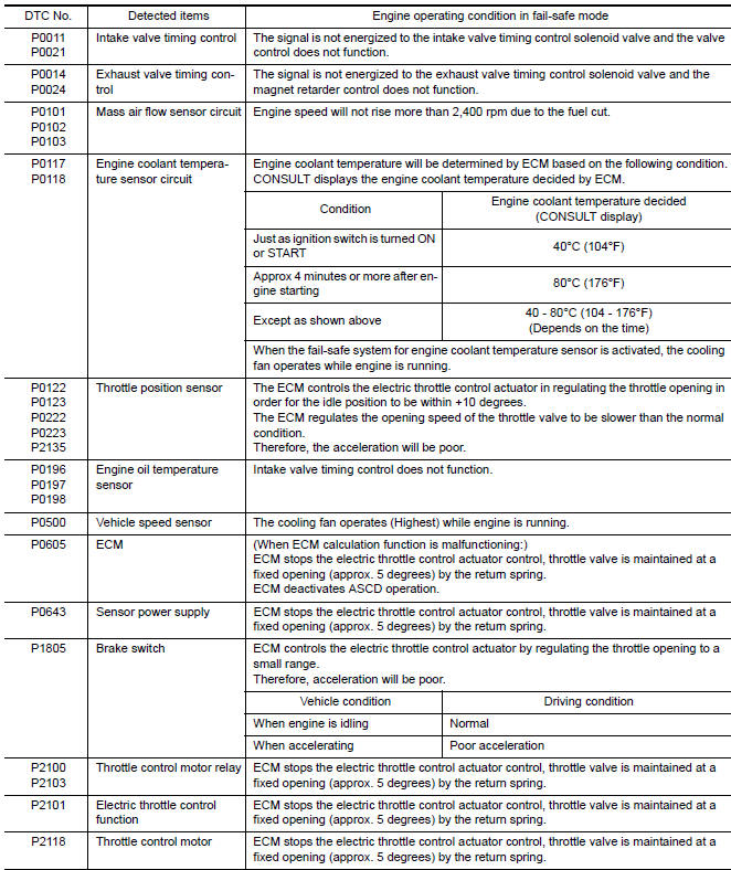
DTC RELATED ITEM
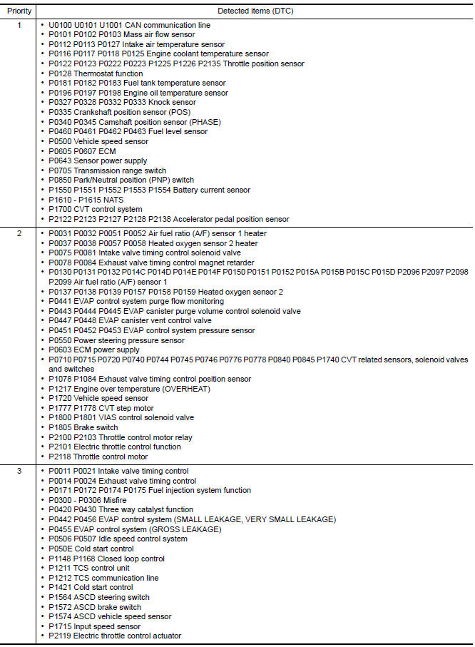
DTC Inspection Priority Chart
If some DTCs are displayed at the same time, perform inspections one by one based on the following priority chart.
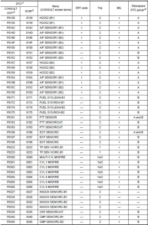
DTC Index
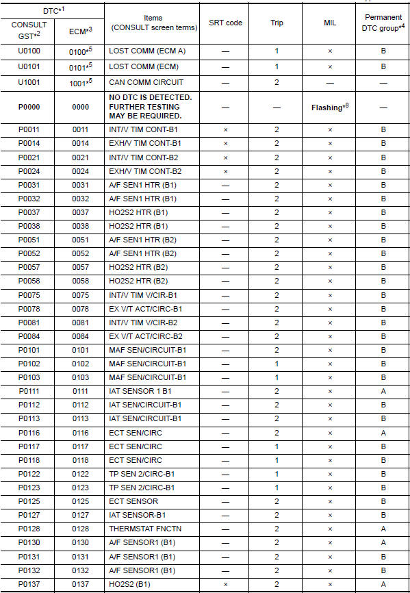
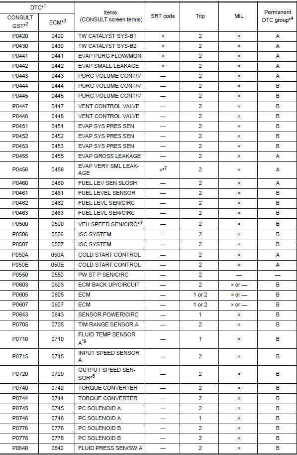
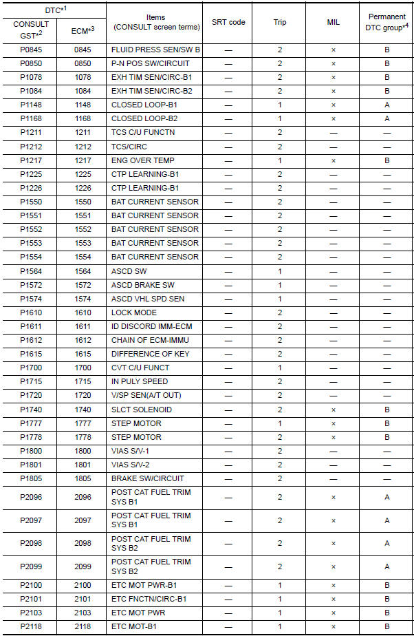
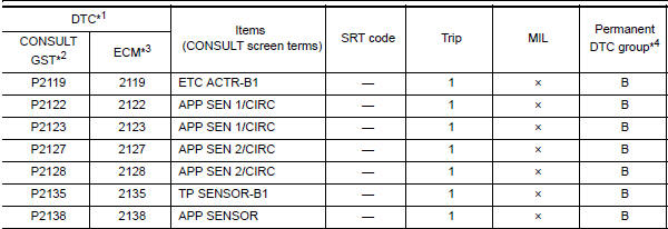
*1: 1st trip DTC No. is the same as DTC No.
*2: This number is prescribed by SAE J2012/ISO 15031-6.
*3: In Diagnostic Test Mode II (Self-diagnostic results), this number is
controlled by NISSAN.
*4: Refer to EC-31, "Description", "HOW TO ERASE PERMANENT DTC".
*5: The troubleshooting for this DTC needs CONSULT.
*6: When the fail-safe operations for both self-diagnoses occur, the MIL
illuminates.
*7: SRT code will not be set if the self-diagnostic result is NG.
*8: When the ECM is in the mode that displays SRT status, MIL may flash. For the
details, refer to "How to Display SRT Status".
*9: When erasing this DTC, always use CONSULT or GST.
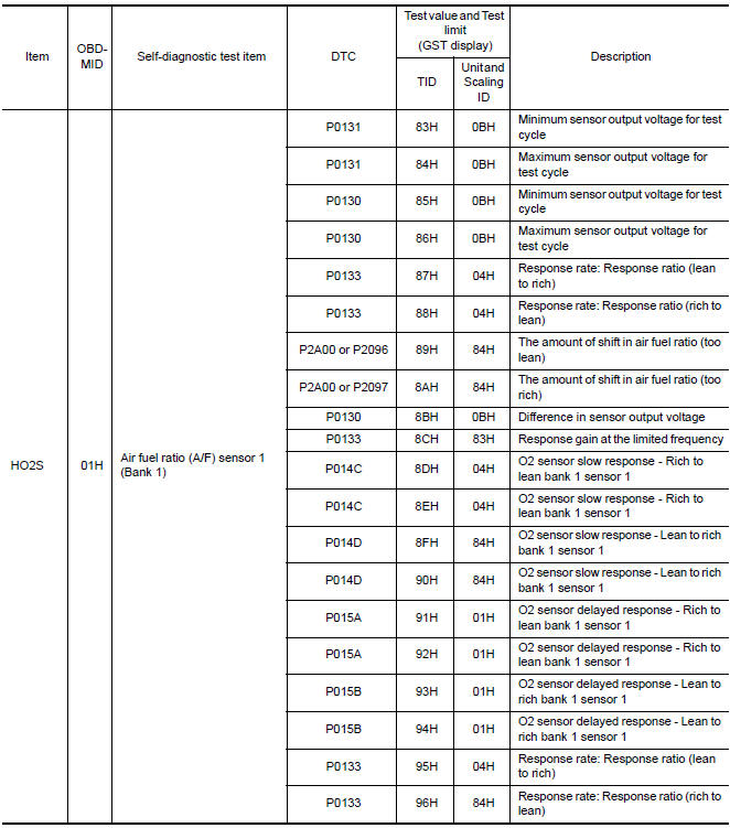
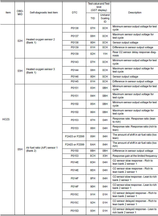
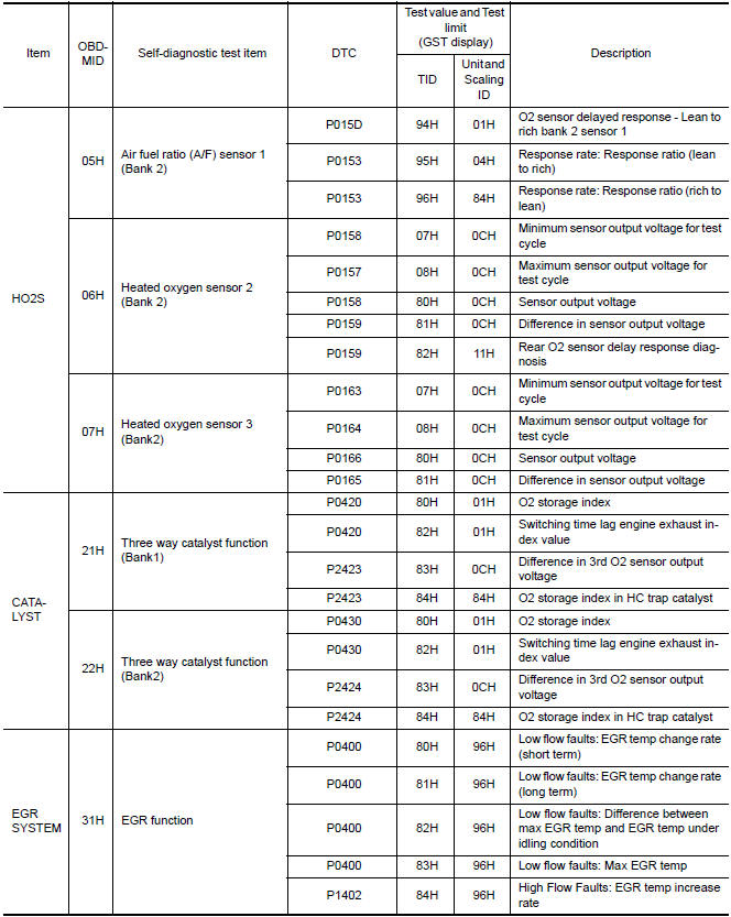
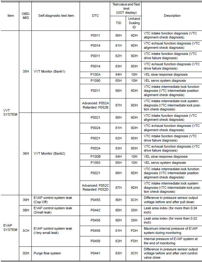
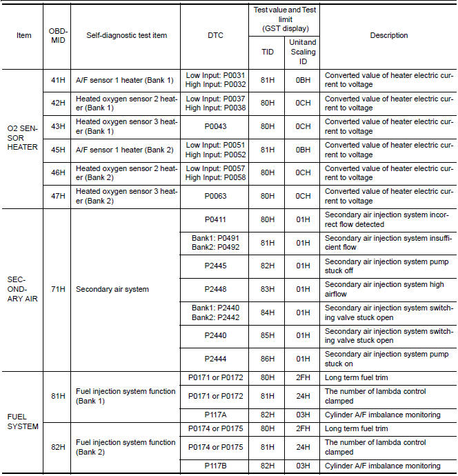
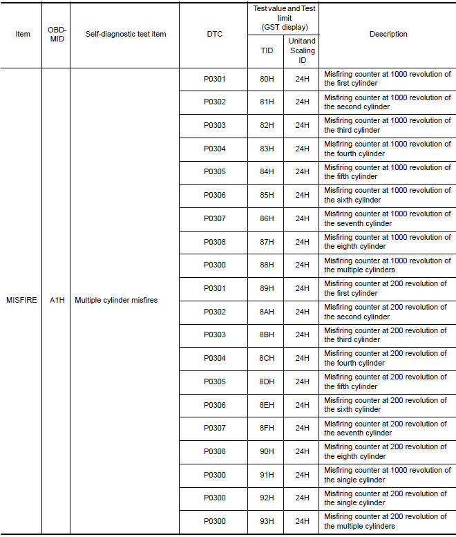
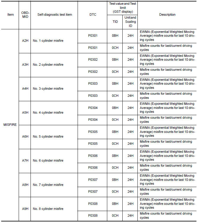
Test Value and Test Limit
The following is the information specified in Service $06 of SAE J1979/ISO 15031-5.
The test value is a parameter used to determine whether a system/circuit diagnostic test is OK or NG while being monitored by the ECM during self-diagnosis. The test limit is a reference value which is specified as the maximum or minimum value and is compared with the test value being monitored.
These data (test value and test limit) are specified by On Board Monitor ID (OBDMID), Test ID (TID), Unit and Scaling ID and can be displayed on the GST screen.
The items of the test value and test limit will be displayed with GST screen which items are provided by the ECM. (e.g., if bank 2 is not applied on this vehicle, only the items of bank 1 are displayed)
 Variable induction air system
Description
Power Valves 1 and 2
The power valves 1 and 2 are installed in intake manifold collector and used to
control the suction passage of
the variable induction air control system. They a ...
 Wiring diagram
ENGINE CONTROL SYSTEM
Wiring Diagram
...
Other materials:
Precaution
PRECAUTIONS
Precaution for Supplemental Restraint System (SRS) "AIR BAG" and "SEAT
BELT
PRE-TENSIONER"
The Supplemental Restraint System such as "AIR BAG" and "SEAT BELT
PRE-TENSIONER", used along
with a front seat belt, helps to reduce the risk or severity of injury to ...
TCM branch line circuit
Diagnosis Procedure
1.CHECK CONNECTOR
Turn the ignition switch OFF.
Disconnect the battery cable from the negative terminal.
Check the following terminals and connectors for damage, bend and
loose connection (unit side and connector
side).
TCM
Harness connector F1
Harness con ...
Precaution
PRECAUTIONS
Precaution for Supplemental Restraint System (SRS) "AIR BAG" and
"SEAT BELT PRE-TENSIONER"
The Supplemental Restraint System such as "AIR BAG" and "SEAT BELT
PRE-TENSIONER", used along with a front seat belt, helps to reduce the risk
or severity of injury to the driver and front ...
Nissan Maxima Owners Manual
- Illustrated table of contents
- Safety-Seats, seat belts and supplemental restraint system
- Instruments and controls
- Pre-driving checks and adjustments
- Monitor, climate, audio, phone and voice recognition systems
- Starting and driving
- In case of emergency
- Appearance and care
- Do-it-yourself
- Maintenance and schedules
- Technical and consumer information
Nissan Maxima Service and Repair Manual

0.0072