Nissan Maxima Service and Repair Manual: Variable induction air system
Description
Power Valves 1 and 2
The power valves 1 and 2 are installed in intake manifold collector and used to
control the suction passage of
the variable induction air control system. They are set in the fully closed or
fully opened position by the power
valve actuators 1 and 2 operated by the vacuum stored in the vacuum tank. The
vacuum to power valve actuators
is controlled by the VIAS control solenoid valves 1 and 2.
Component Function Check
1.CHECK OVERALL FUNCTION-I
With CONSULT
- Start engine and warm it up to the normal operating temperature.
- Perform "VIAS S/V-1" in "ACTIVE TEST" mode with CONSULT.
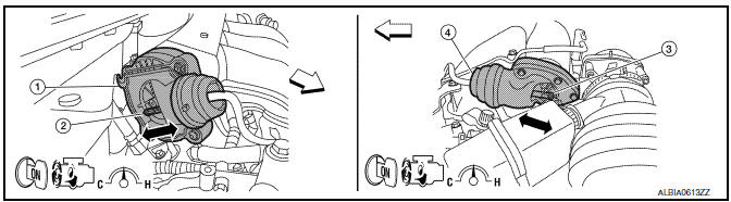
- Turn VIAS control solenoid valve 1 "ON" and "OFF", and check that power valve actuator 1 rod moves.

- Power valve actuator 1
- Power valve actuator 1 rod
- Power valve actuator 2 rod
- Power valve actuator 2
 : Vehicle front
Without CONSULT
- Start engine and warm it up to the normal operating temperature.
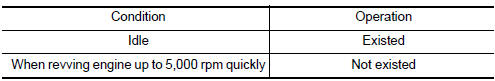
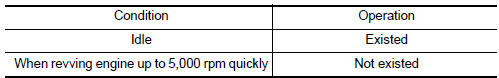
- When revving engine up to 5,000 rpm quickly.
- Check that power valve actuator 1 rod moves under the following conditions.
- Power valve actuator 1
- Power valve actuator 1 rod
- Power valve actuator 2 rod
- Power valve actuator 2
 : Vehicle front
2.CHECK OVERALL FUNCTION-II
With CONSULT
- Perform "VIAS S/V-2" in "ACTIVE TEST" mode with CONSULT.
- Turn VIAS control solenoid valve 2 "ON" and "OFF", and check that power valve actuator 2 rod moves.
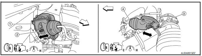
- Power valve actuator 1
- Power valve actuator 1 rod
- Power valve actuator 2 rod
- Power valve actuator 2
 : Vehicle front
Without CONSULT
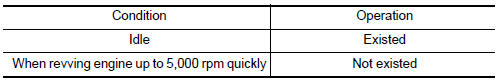
- When revving engine up to 5,000 rpm quickly.
- Check that power valve actuator 2 rod moves under the following conditions.
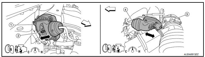
- Power valve actuator 1
- Power valve actuator 1 rod
- Power valve actuator 2 rod
- Power valve actuator 2
 : Vehicle front
Diagnosis Procedure
1.INSPECTION START
Confirm the malfunctioning system (power valve 1 or power valve 2).
2.CHECK VACUUM EXISTENCE-I
With CONSULT
- Stop engine and disconnect vacuum hose connected to power valve actuator 1.
- Start engine and let it idle.
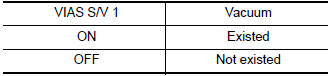
- Perform "VIAS S/V-1" in "ACTIVE TEST" mode with CONSULT.
- Turn VIAS control solenoid valve 1 "ON" and "OFF", and check vacuum existence under the following conditions.
Without CONSULT
- Stop engine and disconnect vacuum hose connected to power valve actuator 1.
- Disconnect VIAS control solenoid valve 1 harness connector.
- Start engine.
- When revving engine up to 5,000 rpm quickly.
- Check vacuum existence under the following conditions.
3.CHECK VACUUM TANK
- Stop engine and disconnect vacuum hose connected to intake manifold collector.
- Start engine and let it idle.
- Check vacuum existence from intake manifold collector.
4.CHECK VACUUM HOSE
- Stop engine.
- Check vacuum hose for cracks, clogging, improper connection or disconnection.
5.CHECK VIAS CONTROL SOLENOID VALVE 1
6.CHECK VACUUM EXISTENCE-II
With CONSULT
- Stop engine and disconnect vacuum hose connected to power valve actuator 2.
- Start engine and let it idle.
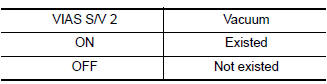
- Perform "VIAS S/V-2" in "ACTIVE TEST" mode with CONSULT.
- Turn VIAS control solenoid valve 2 "ON" and "OFF", and check vacuum existence under the following conditions.
Without CONSULT
- Stop engine and disconnect vacuum hose connected to power valve actuator 2.
- Disconnect VIAS control solenoid valve 1 harness connector.
- Start engine.
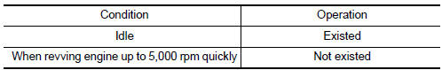
- When revving engine up to 5,000 rpm quickly.
- Check vacuum existence under the following conditions.
7.CHECK VACUUM HOSE
- Stop engine.
- Check vacuum hose for cracks, clogging, improper connection or disconnection.
8.CHECK VIAS CONTROL SOLENOID VALVE 2
9.CHECK INTERMITTENT INCIDENT
 Refrigerant pressure sensor
Description
The refrigerant pressure sensor is installed at the condenser of the air
conditioner system. The sensor uses an
electrostatic volume pressure transducer to convert refrigerant pressur ...
 ECU diagnosis information
ECM
Reference Value
VALUES ON THE DIAGNOSIS TOOL
NOTE:
The following table includes information (items) inapplicable
to this vehicle. For information (items) applicable
to this vehi ...
Other materials:
Exterior lighting system symptoms
Symptom Table
CAUTION: Perform the self-diagnosis with CONSULT
before the symptom diagnosis. Perform the trouble diagnosis if any DTC is
detected.
...
BSW driving situations
Illustration 1 - Approaching from behind
Indicator
on
Indicator
off
Indicator
flashing
Another vehicle approaching from
behind
Illustration 1: The side BSW/RCTA indicator
light illuminates if a vehicle enters the detection
zone from behind in an adjacent lane.
Illustration 2 - ...
Driver Attention Alert system operation
If the system detects driver fatigue or that driver
attention is decreasing, the message "Take a
break?"appears in the vehicle information display
and a chime sounds when the vehicle is driven at
speeds above 37 mph (60 km/h).
The system continuously monitors driver attention
and can pro ...
Nissan Maxima Owners Manual
- Illustrated table of contents
- Safety-Seats, seat belts and supplemental restraint system
- Instruments and controls
- Pre-driving checks and adjustments
- Monitor, climate, audio, phone and voice recognition systems
- Starting and driving
- In case of emergency
- Appearance and care
- Do-it-yourself
- Maintenance and schedules
- Technical and consumer information
Nissan Maxima Service and Repair Manual

0.006