Nissan Maxima Service and Repair Manual: Diagnosis and repair workflow
Work Flow
OVERALL SEQUENCE
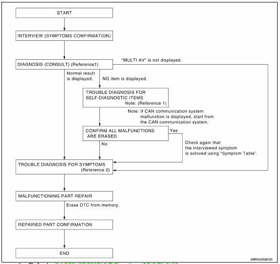
DETAILED FLOW\
1.CHECK SYMPTOM
Check the malfunction symptoms by performing the following items.
- Interview the customer to obtain the malfunction information (conditions and environment when the malfunction occurred).
- Check the symptom.
2.SELF-DIAGNOSIS (CONSULT)
- Connect CONSULT and perform "SELF-DIAGNOSIS" for "MULTI AV". NOTE: Skip to step 4 of the diagnosis procedure if "MULTI AV" is not displayed.
- Check if any DTC No. is displayed in the self-diagnosis results.
3.CHECK SELF-DIAGNOSIS RESULTS (CONSULT)
- Check the DTC No. indicated in the self-diagnosis results.
- Perform the relevant diagnosis referring to the DTC No. list. Refer to AV-437, "DTC Index".
NOTE: Start with the diagnosis for the CAN communication system if "CAN COMM CIRCUIT [U1000] or CONTROL UNIT (CAN) [U1010]" is displayed.
4.PERFORM DIAGNOSIS BY SYMPTOM
Perform the relevant diagnosis referring to the diagnosis chart by symptom.
5.REPAIR OR REPLACE MALFUNCTIONING PARTS
Repair or replace the identified malfunctioning parts.
NOTE: Erase the stored self-diagnosis results after repairing or replacing the relevant components if any DTC No. has been indicated in the self-diagnosis results.
6.CHECK AFTER REPAIR
- Perform self-diagnosis for "MULTI AV" with CONSULT after repairing or replacing the malfunctioning parts.
- Check if any DTC No. is displayed in the self-diagnosis results.
7.FINAL CHECK
Perform the operation check to confirm that the malfunction symptom is solved or that any other symptoms are present.
 Basic inspection
...
 Inspection and adjustment
REAR VIEW MONITOR POSSIBLE ROUTE LINE CENTER POSITION ADJUSTMENT
REAR VIEW MONITOR POSSIBLE ROUTE LINE CENTER POSITION ADJUSTMENT :
Description
Adjust the center position of the possible route lin ...
Other materials:
Tilt motor
Exploded View
Steering column assembly
Telescope motor
Telescope motor link bracket
Tilt motor
Tilt motor bolt cap
Removal and Installation
REMOVAL
Remove instrument lower panel LH. Refer to IP-19, "Removal and
Installation".
Remove lower knee protector (LH) bolts (A) a ...
Front fog lamp circuit
Description
The IPDM E/R (intelligent power distribution module engine room) controls the
front fog lamp relay based on inputs from the BCM over the CAN communication
lines. When the front fog lamp relay is energized, power flows from the front
fog lamp relay in the IPDM E/R to the front fog ...
BCM (body control module)
Reference Value
NOTE: The Signal Tech II Tool (J-50190) can be used
to perform the following functions. Refer to the Signal Tech II User Guide
for additional information.
Activate and display TPMS transmitter IDs
Display tire pressure reported by the TPMS transmitter
Read TPMS DTCs
Re ...
Nissan Maxima Owners Manual
- Illustrated table of contents
- Safety-Seats, seat belts and supplemental restraint system
- Instruments and controls
- Pre-driving checks and adjustments
- Monitor, climate, audio, phone and voice recognition systems
- Starting and driving
- In case of emergency
- Appearance and care
- Do-it-yourself
- Maintenance and schedules
- Technical and consumer information
Nissan Maxima Service and Repair Manual

0.0053