
Nissan Maxima Service and Repair Manual: Inspection and adjustment
REAR VIEW MONITOR POSSIBLE ROUTE LINE CENTER POSITION ADJUSTMENT
REAR VIEW MONITOR POSSIBLE ROUTE LINE CENTER POSITION ADJUSTMENT : Description
Adjust the center position of the possible route line of the rear view monitor if it is shifted.
REAR VIEW MONITOR POSSIBLE ROUTE LINE CENTER POSITION ADJUSTMENT : Special Repair Requirement
1.STEERING OPERATION
Steer the steering wheel to the leftmost and rightmost positions.
2.DRIVING
Drive the vehicle straight ahead 100 m (328.1 ft) or more at a speed of 30 km/h (18.6 MPH) or more.
ADDITIONAL SERVICE WHEN REPLACING CONTROL UNIT
ADDITIONAL SERVICE WHEN REPLACING CONTROL UNIT : Description
BEFORE REPLACEMENT
When replacing AV control unit, save current vehicle specification with CONSULT configuration before replacement.
AFTER REPLACEMENT
CAUTION: When replacing AV control unit, you must perform "WRITE CONFIGURATION" with CONSULT.
- Complete the procedure of "WRITE CONFIGURATION" in order.
- If you set incorrect "WRITE CONFIGURATION", incidents might occur.
- Configuration is different for each vehicle model. Confirm configuration of each vehicle model.
ADDITIONAL SERVICE WHEN REPLACING CONTROL UNIT : Special Repair Requirement
1.SAVING VEHICLE SPECIFICATION
-CONSULT Configuration
Perform "READ CONFIGURATION" to save current vehicle specification
2.REPLACE AV CONTROL UNIT
Replace AV control unit.
3.WRITING VEHICLE SPECIFICATION
-CONSULT Configuration
Perform "WRITE CONFIGURATION - Config file" or "WRITE CONFIGURATION - Manual selection" to write vehicle specification.
4.OPERATION CHECK
Check that the operation of the AV control unit and camera images (fixed guide lines and predictive course lines) are normal.
CONFIGURATION (AV CONTROL UNIT)
CONFIGURATION (AV CONTROL UNIT) : Description
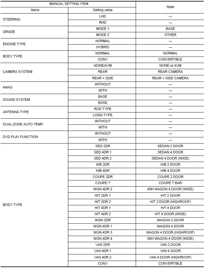
- Since vehicle specifications are not included in the AV control unit after replacement, it is required to write vehicle specifications with CONSULT.
- Configuration has three functions as follows.
| Function | Description |
| READ CONFIGURATION |
|
| WRITE CONFIGURATION-Manual selection | Writes the vehicle configuration with manual selection. |
| WRITE CONFIGURATION-Config file | Writes the vehicle configuration with saved data. |
CONFIGURATION (AV CONTROL UNIT) : Special Repair Requirement
1.WRITING MODE SELECTION
CONSULT Configuration
Select "CONFIGURATION" of AV control unit.
2.PERFORM "WRITE CONFIGURATION-CONFIG FILE"
CONSULT Configuration
Perform "WRITE CONFIGURATION-Config file".
3.PERFORM "WRITE CONFIGURATION-MANUAL SELECTION"
CONSULT Configuration
Select "WRITE CONFIGURATION-Manual selection" to write vehicle specifications into the AV control unit.
4.OPERATION CHECK
Check that the operation of the AV control unit and camera images (fixed guide lines and predictive course lines) are normal.
CONFIGURATION (AV CONTROL UNIT) : Configuration List
CAUTION: Check vehicle specifications before servicing.
 Diagnosis and repair workflow
Work Flow
OVERALL SEQUENCE
DETAILED FLOW\
1.CHECK SYMPTOM
Check the malfunction symptoms by performing the following items.
Interview the customer to obtain the malfunction information
(c ...

Other materials:
Combination meter
Removal and Installation
REMOVAL
Disconnect the negative battery terminal. Refer
to PG-67, "Removal and Installation (Battery)".
Remove the cluster lid A. Refer to IP-16,
"Removal and Installation".
Remove the combination meter screws (A) using
powe ...
C1147, C1148, C1149, C1150 USV/HSV line
Description
USV1, USV2 (CUT VALVE)
The cut valve shuts off the normal brake fluid path from the master cylinder,
when VDC/TCS is activated.
HSV1, HSV2 (SUCTION VALVE)
The suction valve supplies the brake fluid from the master cylinder to the
pump, when VDC/TCS is activated.
DTC Logic
DTC D ...
IPDM E/R (intelligent power distribution module engine room)
Reference Value
VALUES ON THE DIAGNOSIS TOOL
TERMINAL LAYOUT
PHYSICAL VALUES
Fail Safe
CAN COMMUNICATION CONTROL
When CAN communication with ECM and BCM is impossible, IPDM E/R performs
fail-safe control. After CAN communication recovers normally, it also returns
to nor ...
Nissan Maxima Owners Manual
- Illustrated table of contents
- Safety-Seats, seat belts and supplemental restraint system
- Instruments and controls
- Pre-driving checks and adjustments
- Monitor, climate, audio, phone and voice recognition systems
- Starting and driving
- In case of emergency
- Appearance and care
- Do-it-yourself
- Maintenance and schedules
- Technical and consumer information
Nissan Maxima Service and Repair Manual

0.0086