Nissan Maxima Service and Repair Manual: Wiring diagram
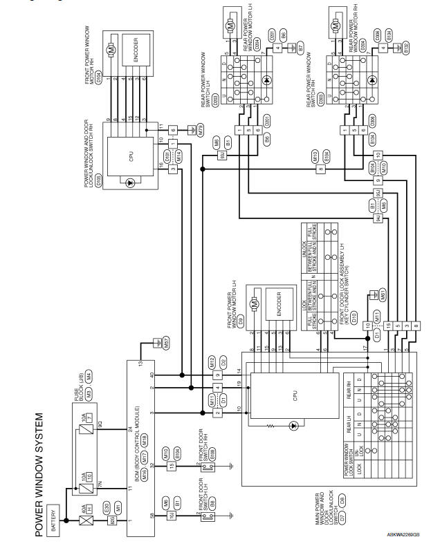
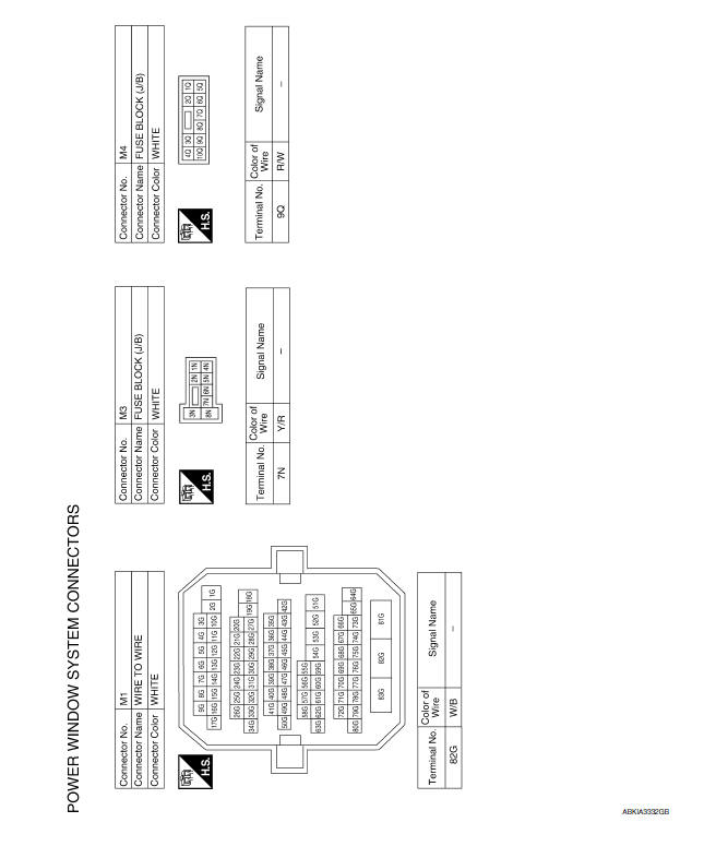
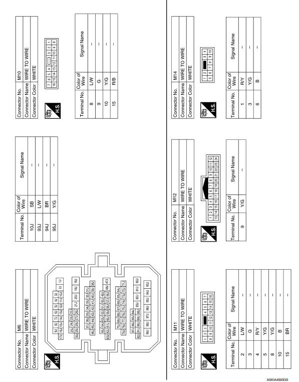
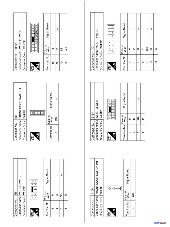
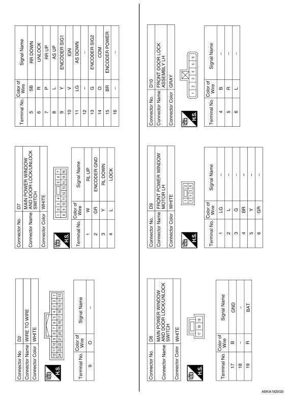
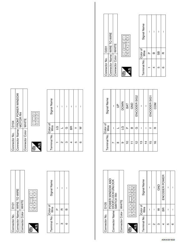
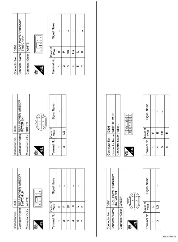
POWER WINDOW SYSTEM
Wiring Diagram
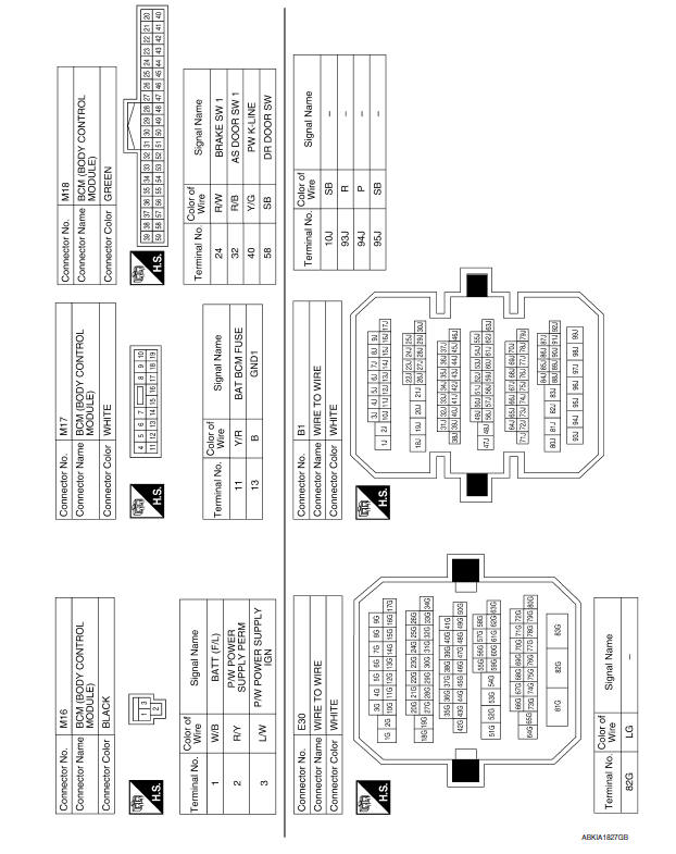
 BCM (body control module)
Reference Value
NOTE:
The Signal Tech II Tool (J-50190) can be used to perform the following
functions. Refer to the Signal Tech II
User Guide for additional information.
Activate and displ ...

Other materials:
P0710 transmission fluid temperature sensor A
Description
The CVT fluid temperature sensor detects the CVT fluid temperature and sends
a signal to the TCM.
DTC Logic
DTC DETECTION LOGIC
DTC CONFIRMATION PROCEDURE
CAUTION: Always drive vehicle at a safe speed.
NOTE: Immediately after performing any "DTC CONFIRMATION
PROCEDURE", alway ...
Front wiper and washer system symptoms
Symptom Table
CAUTION:Perform the self-diagnosis with CONSULT
before performing the diagnosis by symptom. Perform thediagnosis by DTC if
DTC is detected.
...
Turn signal lamp circuit
Description
The BCM monitors inputs from the combination switch to determine when to
activate the turn signals. The BCM outputs voltage direction to the left and
right turn signals during turn signal operation or both during hazard warning
operation. The BCM sends a turn signal indicator requ ...
Nissan Maxima Owners Manual
- Illustrated table of contents
- Safety-Seats, seat belts and supplemental restraint system
- Instruments and controls
- Pre-driving checks and adjustments
- Monitor, climate, audio, phone and voice recognition systems
- Starting and driving
- In case of emergency
- Appearance and care
- Do-it-yourself
- Maintenance and schedules
- Technical and consumer information
Nissan Maxima Service and Repair Manual

0.007