Nissan Maxima Service and Repair Manual: P2127, P2128 APP sensor
Description
The accelerator pedal position sensor is installed on the upper end of the accelerator pedal assembly. The sensor detects the accelerator position and sends a signal to the ECM.
Accelerator pedal position sensor has two sensors. These sensors are a kind of potentiometer which transform the accelerator pedal position into output voltage, and emit the voltage signal to the ECM.
In addition, these sensors sends opening and closing speed of the accelerator pedal and feed the voltage signals to the ECM. The ECM judges the current opening angle of the accelerator pedal from these signals and controls the throttle control motor based on these signals.
Idle position of the accelerator pedal is determined by the ECM receiving the signal from the accelerator pedal position sensor. The ECM uses this signal for engine operations such as fuel cut.
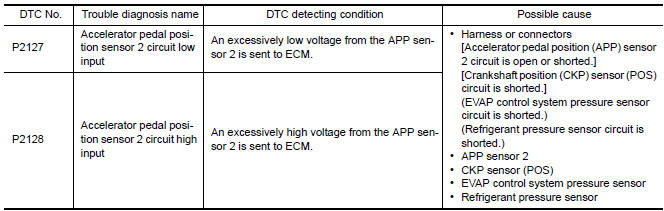
DTC Logic
DTC DETECTION LOGIC
DTC CONFIRMATION PROCEDURE
1.PRECONDITIONING
If DTC Confirmation Procedure has been previously conducted, always perform the following before conducting the next test.
- Turn ignition switch OFF and wait at least 10 seconds.
- Turn ignition switch ON.
- Turn ignition switch OFF and wait at least 10 seconds.
TESTING CONDITION: Before performing the following procedure, confirm that battery voltage is more than 8 V at idle.
2.PERFORM DTC CONFIRMATION PROCEDURE
- Start engine and let it idle for 1 second.
- Check DTC.
Diagnosis Procedure
Regarding Wiring Diagram information
1.CHECK GROUND CONNECTION
- Turn ignition switch OFF.
- Check ground connection E9.
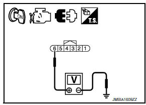
2.CHECK APP SENSOR 2 POWER SUPPLY CIRCUIT-I
- Disconnect accelerator pedal position (APP) sensor harness connector.
- Turn ignition switch ON.
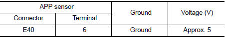
- Check the voltage between APP sensor harness connector and ground.
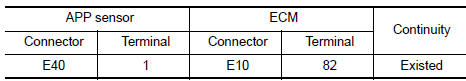
3.CHECK APP SENSOR 2 POWER SUPPLY CIRCUIT-II
- Turn ignition switch OFF.
- Disconnect ECM harness connector.
- Check the continuity between APP sensor harness connector and ECM harness connector.
4.CHECK SENSOR POWER SUPPLY CIRCUIT
Check harness for short to power and short to ground, between the following terminals.
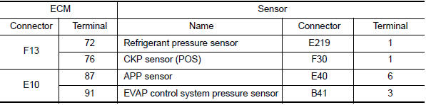
5.CHECK COMPONENTS
Check the following.
- Crankshaft position sensor (POS) (Refer to EC-299, "Component Inspection".)
- EVAP control system pressure sensor (Refer to EC-346, "Component Inspection".)
- Refrigerant pressure sensor
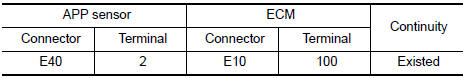
6.CHECK APP SENSOR 2 GROUND CIRCUIT FOR OPEN AND SHORT
- Turn ignition switch OFF.
- Disconnect ECM harness connector.
- Check the continuity between APP sensor harness connector and ECM harness connector.
- Also check harness for short to ground and short to power.
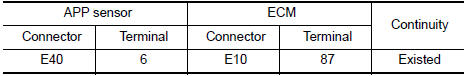
7.CHECK APP SENSOR 2 INPUT SIGNAL CIRCUIT FOR OPEN AND SHORT
- Check the continuity between APP sensor harness connector and ECM harness connector.
- Also check harness for short to ground and short to power.
8.CHECK APP SENSOR
9.REPLACE ACCELERATOR PEDAL ASSEMBLY
- Replace accelerator pedal assembly
10.CHECK INTERMITTENT INCIDENT
Component Inspection
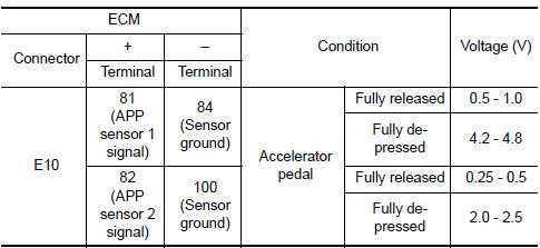
1.CHECK ACCELERATOR PEDAL POSITION SENSOR
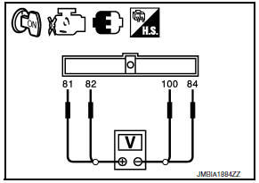
- Reconnect all harness connectors disconnected.
- Turn ignition switch ON.
- Check the voltage between ECM harness connector terminals under the following conditions.
2.REPLACE ACCELERATOR PEDAL ASSEMBLY
- Replace accelerator pedal assembly.
Special Repair Requirement
1.PERFORM ACCELERATOR PEDAL RELEASED POSITION LEARNING
2.PERFORM THROTTLE VALVE CLOSED POSITION LEARNING
3.PERFORM IDLE AIR VOLUME LEARNING
 P2122, P2123 APP sensor
Description
The accelerator pedal position sensor is installed on the upper end
of the accelerator pedal assembly. The sensor detects the accelerator
position and sends a signal to the ECM.
Ac ...
 P2135 TP sensor
Description
Electric throttle control actuator consists of throttle control motor,
throttle position sensor, etc. The throttle position sensor responds to
the throttle valve movement.
The thr ...
Other materials:
Door
FRONT DOOR
FRONT DOOR : Exploded View
Front door panel
Front door check link
Front door lower hinge
Front lower hinge
Grease
FRONT DOOR : Removal and Installation
CAUTION:
Use two people when removing or installing the front door
assembly due to its heavy weight. ...
Radiator
Exploded View
Radiator
CVT oil cooler hose
Radiator drain plug
Radiator hose (lower) clamp
Radiator hose (lower)
Radiator hose (lower) bracket
Reservoir tank
Reservoir hose
Radiator cap
Radiator cap adaptor
Radiator hose (upper)
Radiator hose (upper) clamp
&nb ...
On board diagnostic (OBD) system
Diagnosis Description
DESCRIPTION
The CVT system has two self-diagnostic systems.
The first is the emission-related on board diagnostic system (OBD-II) performed
by the TCM in combination
with the ECM. A malfunction is indicated by the MIL (Malfunction Indicator Lamp)
and is stored as a D ...
Nissan Maxima Owners Manual
- Illustrated table of contents
- Safety-Seats, seat belts and supplemental restraint system
- Instruments and controls
- Pre-driving checks and adjustments
- Monitor, climate, audio, phone and voice recognition systems
- Starting and driving
- In case of emergency
- Appearance and care
- Do-it-yourself
- Maintenance and schedules
- Technical and consumer information
Nissan Maxima Service and Repair Manual

0.0055