Nissan Maxima Service and Repair Manual: C1708 - C1711 data from transmitter not being received
Description
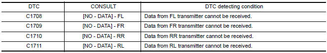
Tire pressure data for one or more transmitters is not being received by the BCM.
DTC Logic
NOTE: The Signal Tech II Tool (J-50190) can be used to perform the following functions. Refer to the Signal Tech II User Guide for additional information.
- Activate and display TPMS transmitter IDs
- Display tire pressure reported by the TPMS transmitter
- Read TPMS DTCs
- Register TPMS transmitter IDs
DTC DETECTION LOGIC
DTC CONFIRMATION PROCEDURE
1.ID REGISTRATION AND VEHICLE DRIVING
- Carry out ID registration of all transmitters. Refer to WT-6, "ID Registration Procedure".
- Drive at a speed of 40 km/h (25 MPH) or more for 3 minutes, and then drive the vehicle at any speed for 10 minutes.
- Check all tire pressures with CONSULT within 5 minutes.
Diagnosis Procedure
NOTE: The Signal Tech II Tool (J-50190) can be used to perform the following functions. Refer to the Signal Tech II User Guide for additional information.
- Activate and display TPMS transmitter IDs
- Display tire pressure reported by the TPMS transmitter
- Read TPMS DTCs
- Register TPMS transmitter IDs
MALFUNCTION CODE NO. 21, 22, 23 OR 24 (DTC C1708, C1709, C1710 OR C1711)
1.CHECK BCM
Drive for several minutes. Check all tire pressures with CONSULT.
2.CHECK TIRE PRESSURE RECEIVER CONNECTOR
Check tire pressure receiver connector for damage or loose connections.
3.PERFORM ID REGISTRATION
Carry out ID registration of all transmit
4.DRIVE VEHICLE
- Drive at a speed of 40 km/h (25 MPH) or more for several minutes without stopping.
- Check
5.ID REGISTRATION AND VEHICLE DRIVING
- Carry out ID registration of all transmitters. Refer to WT-6, "ID Registration Procedure".
- Drive at a speed of 40 km/h (25 MPH) or more for 3 minutes, and then drive the vehicle at any speed for 10 minutes.
- Check all tire pressures with CONSULT within 5 minutes.
Special Repair Requirement
Perform preliminary check.

 C1712 - C1715, C1720 - C1723, C1724 - C1727 transmitter malfunction
Description
One or more transmitters are malfunctioning internally.
DTC Logic
NOTE: The Signal Tech II Tool (J-50190) can be used
to perform the following functions. Refer to the Signal Tech II U ...
Other materials:
Bose speaker AMP\
Removal and Installation
Bose speaker amp.
Screws
REMOVAL
NOTE:
If removing the BOSE speaker amp. bracket, it is necessary to remove the parcel
shelf finisher. The BOSE
speaker amp. can be removed without removing the BOSE speaker amp. bracket.
Disconnect the battery negativ ...
U1000 CAN comm circuit
Description
CAN (Controller Area Network) is a serial communication line for real time
application. It is an on-vehicle multiplex
communication line with high data communication speed and excellent error
detection ability. Many electronic
control units are equipped onto a vehicle, and each co ...
Refrigerant pressure sensor
Removal and Installation
REMOVAL
Discharge the refrigerant. Refer to HA-28, "Recycle Refrigerant".
Remove the core support upper cover.
Disconnect the harness connector from the refrigerant pressure
sensor.
Remove the refrigerant pressure sensor.
CAUTION:
Cap or wrap the ...
Nissan Maxima Owners Manual
- Illustrated table of contents
- Safety-Seats, seat belts and supplemental restraint system
- Instruments and controls
- Pre-driving checks and adjustments
- Monitor, climate, audio, phone and voice recognition systems
- Starting and driving
- In case of emergency
- Appearance and care
- Do-it-yourself
- Maintenance and schedules
- Technical and consumer information
Nissan Maxima Service and Repair Manual

0.0054