Nissan Maxima Service and Repair Manual: C1712 - C1715, C1720 - C1723, C1724 - C1727 transmitter malfunction
Description
One or more transmitters are malfunctioning internally.
DTC Logic
NOTE: The Signal Tech II Tool (J-50190) can be used to perform the following functions. Refer to the Signal Tech II User Guide for additional information.
- Activate and display TPMS transmitter IDs
- Display tire pressure reported by the TPMS transmitter
- Read TPMS DTCs
- Register TPMS transmitter IDs
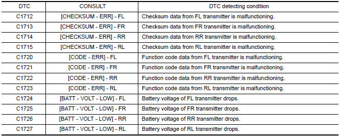
DTC DETECTION LOGIC
DTC CONFIRMATION PROCEDURE
1.DRIVE VEHICLE
- Drive at a speed of 40 km/h (25 MPH) or more for 3 minutes, and then drive the vehicle at any speed for 10 minutes.
- Check all tire pressures with CONSULT within 5 minutes.
Diagnosis Procedure
NOTE: The Signal Tech II Tool (J-50190) can be used to perform the following functions. Refer to the Signal Tech II User Guide for additional information.
- Activate and display TPMS transmitter IDs
- Display tire pressure reported by the TPMS transmitter
- Read TPMS DTCs
- Register TPMS transmitter IDs
MALFUNCTION CODE NO. 31, 32, 33, 34, 41, 42, 43, 44, 45, 46, 47 OR 48 (DTC C1712, C1713, C1714, C1715, C1720, C1721, C1722, C1723, C1724, C1725, C1726 OR C1727)
1.PERFORM ID REGISTRATION
- Carry out ID registration of all transmitters. Refer to WT-6, "ID Registration Procedure".
- Drive at a speed of 40 km/h (25 MPH) or more for 3 minutes, and then drive the vehicle at any speed for 10 minutes.
2.REPLACE TRANSMITTER
- Check low tire pressure warning lamp again for flashing, replace malfunctioning transmitter. Refer to WT- 62, "Removal and Installation".
- Carry out ID registration of all transmitters
3.DRIVE VEHICLE
- Drive at a speed of 40 km/h (25 MPH) or more for 3 minutes, and then drive the vehicle at any speed for 10 minutes.
- Check all tire pressures with CONSULT within 5 minutes
Special Repair Requirement
Perform preliminary check.
 C1708 - C1711 data from transmitter not being received
Description
Tire pressure data for one or more transmitters is not being received by the
BCM.
DTC Logic
NOTE: The Signal Tech II Tool (J-50190) can
be used to perform the following functions. R ...
 C1716 - C1719 transmitter pressure malfunction
Description
Air pressure data from one or more transmitters is out of range.
DTC Logic
NOTE: The Signal Tech II Tool (J-50190) can
be used to perform the following functions. Refer to the Signal ...
Other materials:
Around View Monitor system operation
With the ignition switch in the ON position, move
the shift lever to the R (Reverse) position or press
the CAMERA button to operate the Around
View Monitor.
When the camera is first activated with the bird'seye
view in the display, a red icon (if so equipped)
will flash on the screen. This i ...
B2608 starter relay
Description
Located in IPDM E/R, it runs the starter motor. The
starter relay is turned ON by the BCM when the ignition
switch is in START position. IPDM E/R transmits the starter relay ON signal to
BCM via CAN communication.
DTC Logic
DTC DETECTION LOGIC
NOTE:
If DTC B2608 is displ ...
Steering switch
Description
When one of the steering wheel audio control switches is pushed, the
resistance in the steering wheel audio control switch circuit changes,
depending on which button is pushed.
Diagnosis Procedure
1.CHECK STEERING SWITCH RESISTANCE
Disconnect steering switch connector M88. ...
Nissan Maxima Owners Manual
- Illustrated table of contents
- Safety-Seats, seat belts and supplemental restraint system
- Instruments and controls
- Pre-driving checks and adjustments
- Monitor, climate, audio, phone and voice recognition systems
- Starting and driving
- In case of emergency
- Appearance and care
- Do-it-yourself
- Maintenance and schedules
- Technical and consumer information
Nissan Maxima Service and Repair Manual

0.0065