Nissan Maxima Service and Repair Manual: RGB (B: blue) signal circuit
Description
Transmit the image displayed with AV control unit with RGB signal to the display unit.
Diagnosis Procedure
1.CHECK CONTINUITY RGB (B: BLUE) SIGNAL CIRCUIT
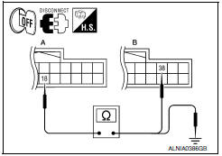
- Turn ignition switch OFF.
- Disconnect display unit connector M141 and AV control unit connector M117.
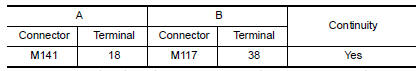
- Check continuity between display unit harness connector M141 (A) terminal 18 and AV control unit harness connector M117 (B) terminal 38.
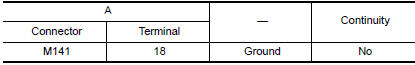
- Check continuity between display unit harness connector M141 (A) terminal 18 and ground.
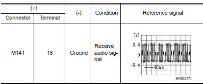
2.CHECK RGB (B: BLUE) SIGNAL
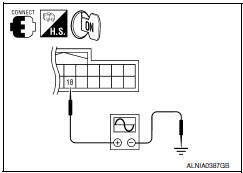
- Connect display unit connector M141 and AV control unit connector M117.
- Turn ignition switch ON.
- Check signal between display unit harness connector M141 terminal 18 and ground.
 RGB (G: green) signal circuit
Description
Transmit the image displayed with AV control unit with RGB signal to the
display unit.
Diagnosis Procedure
1.CHECK CONTINUITY RGB (G: GREEN) SIGNAL CIRCUIT
Turn ignition switc ...
 RGB synchronizing signal circuit
Description
Transmit the RGB synchronizing signal to the display unit so as to
synchronize the RGB image displayed with AV control unit.
Diagnosis Procedure
1.CHECK CONTINUITY RGB SYNCHRONIZING S ...
Other materials:
Parking brake shoe
Exploded View
Back plate
Parking brake shoe (front)
Adjuster
Adjuster spring
Return spring
Anti-rattle spring
Retainer
Anti-rattle pin
Toggle lever
Parking brake shoe (rear)
Front
Apply PBC (Poly Butyl Cuprysil)
grease or silicone based grease
Removal ...
U1300 AV comm circuit
Description
U1300 is indicated when a communication signal malfunction occurs. U1300 is
indicated along with DTCs that
identify components connected to the AV control unit through communication
lines. Determine the possible
malfunction cause from the table below.
SELF-DIAGNOSIS RESULTS DIS ...
Unexpected pedal reaction
Diagnosis Procedure
1.CHECK BRAKE PEDAL STROKE
Check brake pedal stroke.
2.CHECK FUNCTION
Disconnect ABS actuator and electric unit (control unit) connector to
deactivate ABS. Check if braking force is
normal in this condition.Connect connector after inspection.
3.CHECK WHEEL SENSOR AND SEN ...
Nissan Maxima Owners Manual
- Illustrated table of contents
- Safety-Seats, seat belts and supplemental restraint system
- Instruments and controls
- Pre-driving checks and adjustments
- Monitor, climate, audio, phone and voice recognition systems
- Starting and driving
- In case of emergency
- Appearance and care
- Do-it-yourself
- Maintenance and schedules
- Technical and consumer information
Nissan Maxima Service and Repair Manual

0.0057