Nissan Maxima Service and Repair Manual: RGB synchronizing signal circuit
Description
Transmit the RGB synchronizing signal to the display unit so as to synchronize the RGB image displayed with AV control unit.
Diagnosis Procedure
1.CHECK CONTINUITY RGB SYNCHRONIZING SIGNAL CIRCUIT
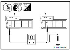
- Turn ignition switch OFF.
- Disconnect display unit connector M141 and AV control unit connector M117.
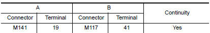
- Check continuity between display unit harness connector M141 (A) terminal 19 and AV control unit harness connector M117 (B) terminal 41.
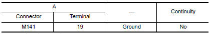
- Check continuity between display unit harness connector M141 (A) terminal 19 and ground.
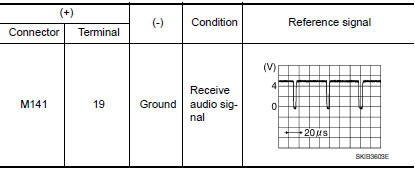
2.CHECK RGB SYNCHRONIZING SIGNAL
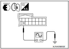
- Connect display unit connector M141 and AV control unit connector M117.
- Turn ignition switch ON.
- Check signal between display unit harness connector M141 terminal 19 and ground.
 RGB (B: blue) signal circuit
Description
Transmit the image displayed with AV control unit with RGB signal to the
display unit.
Diagnosis Procedure
1.CHECK CONTINUITY RGB (B: BLUE) SIGNAL CIRCUIT
Turn ignition switch ...
 RGB AREA (YS) signal circuit
Description
Transmits the display area of RGB image displayed by AV control unit with RGB
area (YS) signal to display unit.
Diagnosis Procedure
1.CHECK CONTINUITY RGB AREA (YS) SIGNAL CIRCUIT
...
Other materials:
B1033 - B1035 crash zone sensor
Description
DTC B1033 - B1035 CRASH ZONE SENSOR
The crash zone sensor is wired to the air bag diagnosis sensor unit. The air
bag diagnosis sensor unit willmonitor for opens and shorts in detected lines
to the crash zone sensor.
PART LOCATION
DTC Logic
DTC DETECTION LOGIC
With CONSULT
DT ...
Opening windows
The Intelligent Key allows you to simultaneously
open windows equipped with automatic operation.
To open the windows, press and hold
the button on the Intelligent
Key for
longer than 3 seconds.
The door windows will lower while holding down
the button on the Intelligent Key.
NOTE: ...
P0101 MAF sensor
Description
The mass air flow sensor (1) is placed in the stream of intake air. It
measures the intake flow rate by measuring a part of the entire
intake flow. The mass air flow sensor controls the temperature of the
hot wire to a certain amount. The heat generated by the hot wire is ...
Nissan Maxima Owners Manual
- Illustrated table of contents
- Safety-Seats, seat belts and supplemental restraint system
- Instruments and controls
- Pre-driving checks and adjustments
- Monitor, climate, audio, phone and voice recognition systems
- Starting and driving
- In case of emergency
- Appearance and care
- Do-it-yourself
- Maintenance and schedules
- Technical and consumer information
Nissan Maxima Service and Repair Manual

0.0064