Nissan Maxima Service and Repair Manual: RGB AREA (YS) signal circuit
Description
Transmits the display area of RGB image displayed by AV control unit with RGB area (YS) signal to display unit.
Diagnosis Procedure
1.CHECK CONTINUITY RGB AREA (YS) SIGNAL CIRCUIT
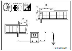
- Turn ignition switch OFF.
- Disconnect display unit connector M141 and AV control unit connector M117.
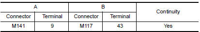
- Check continuity between display unit harness connector M141 (A) terminal 9 and AV control unit harness connector M117 (B) terminal 43.
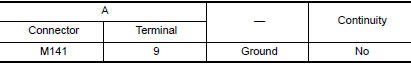
- Check continuity between display unit harness connector M141 (A) terminal 9 and ground.
2.CHECK RGB SYNCHRONIZING SIGNAL
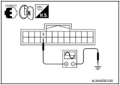
- Connect display unit connector M141 and AV control unit connector M117.
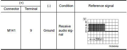
- Turn ignition switch ON.
- Check signal between display unit harness connector M141 terminal 9 and ground.
 RGB synchronizing signal circuit
Description
Transmit the RGB synchronizing signal to the display unit so as to
synchronize the RGB image displayed with AV control unit.
Diagnosis Procedure
1.CHECK CONTINUITY RGB SYNCHRONIZING S ...
 Horizontal synchronizing (HP) signal circuit
Description
In composite image (AUX image, camera image), transmit the vertical
synchronizing (VP) signal and horizontal synchronizing (HP) signal from
display unit to AV control unit so as to sy ...
Other materials:
Fuel level sensor signal circuit
Description
The fuel level sensor unit and fuel pump (fuel level
sensor) detects the approximate fuel level in the fuel tank
and transmits the fuel level signal to the combination meter.
Component Function Check
1.COMBINATION METER INPUT SIGNAL
Select "METER/M&A" on CONSULT.
...
BCM (body control module)
Reference Value
NOTE:
The Signal Tech II Tool (J-50190) can be used to perform the
following functions. Refer to the Signal Tech II
User Guide for additional information.
Activate and display TPMS transmitter IDs
Display tire pressure reported by the TPMS transmitter
Read TPMS DTCs
R ...
Air mix door control system
System Diagram
System Description
The air mix doors are automatically controlled so that in-vehicle temperature
is maintained at a predetermined
value by the temperature setting, ambient temperature, intake temperature and
amount of sunload.
SYSTEM OPERATION
The A/C auto amp. receive ...
Nissan Maxima Owners Manual
- Illustrated table of contents
- Safety-Seats, seat belts and supplemental restraint system
- Instruments and controls
- Pre-driving checks and adjustments
- Monitor, climate, audio, phone and voice recognition systems
- Starting and driving
- In case of emergency
- Appearance and care
- Do-it-yourself
- Maintenance and schedules
- Technical and consumer information
Nissan Maxima Service and Repair Manual

0.0054