Nissan Maxima Service and Repair Manual: Front door speaker
Description
The AV control unit sends audio signals to the BOSE speaker amp. The BOSE speaker amp. amplifies the audio signals before sending them to the front door speakers using the audio signal circuits.
Diagnosis Procedure
1.CONNECTOR CHECK
Check the AV control unit, BOSE speaker amp. and speaker connectors for the following:
- Proper connection
- Damage
- Disconnected or loose terminals
2.HARNESS CHECK
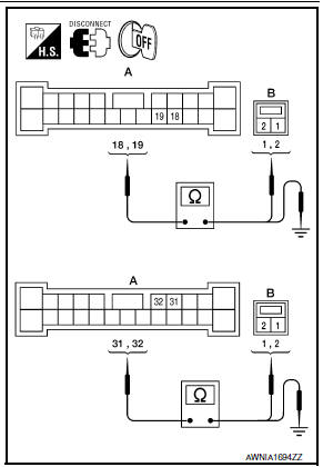
- Disconnect BOSE speaker amp. connector B109 and suspect speaker connector.
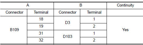
- Check continuity between BOSE speaker amp. harness connector B109 (A) and suspect speaker harness connector (B).
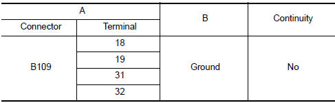
- Check continuity between BOSE speaker amp. harness connector B109 (A) and ground.
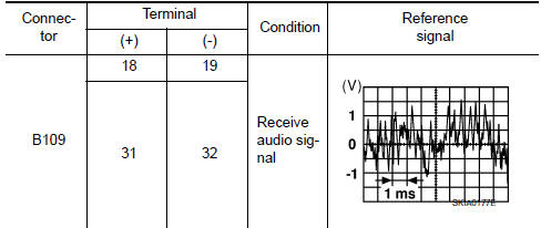
3.FRONT DOOR SPEAKER SIGNAL CHECK
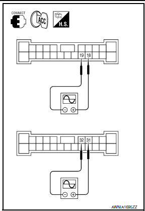
- Connect BOSE speaker amp. connector B109 and suspect speaker connector.
- Turn ignition switch to ACC.
- Push POWER switch.
- Check the signal between BOSE speaker amp. harness connector B109 terminals with CONSULT or oscilloscope.
4.HARNESS CHECK
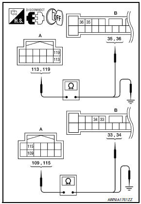
- Disconnect AV control unit connector M157 and BOSE speaker amp. connector B109.
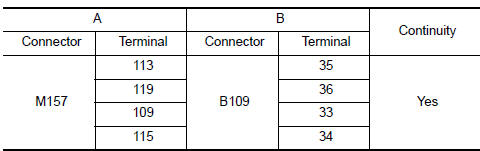
- Check continuity between AV control unit harness connector M157 (A) and BOSE speaker amp. harness connector B109 (B).
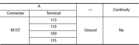
- Check continuity between AV control unit harness connector M157 (A) and ground.
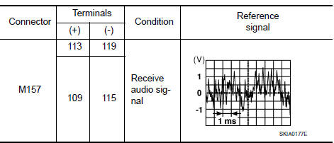
5.FRONT DOOR SPEAKER SIGNAL CHECK
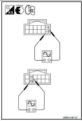
- Connect AV control unit connector and BOSE speaker amp.
connector.
- Turn ignition switch to ACC.
- Push POWER switch.
- Check the signal between AV control unit harness connector terminals with CONSULT or oscilloscope.
 Vertical synchronizing (VP) signal circuit
Description
In composite image (AUX image, camera image), transmit the vertical
synchronizing (VP) signal and horizontal
synchronizing (HP) signal from display unit to AV control unit so as to
...
 Tweeter
Description
The AV control unit sends audio signals to the BOSE speaker amp. The BOSE
speaker amp. amplifies the
audio signals before sending them to the tweeters using the audio signal
circuit ...
Other materials:
Roof finisher
Removal and Installation
REMOVAL
Open the glass lid.
Apply protective tape around the roof side finisher to protect the
surface from damage.
Cut adhesive.
Pass piano wire through the adhesive with a wire pierce.
Tie piano wire on both ends to assist in wire grip.
Pull piano wir ...
Climate controlled seat switches (if so equipped)
The climate controlled seat warms up or cools
down the front seat by blowing warm or cool air
from under the surface of the seat. The climate
control switch is located on the center console.
The climate controlled seat can be operated as
follows:
1. Start the engine.
2. Turn the contr ...
Battery replacement
CAUTION
Be careful not to allow children to swallow
the battery or removed parts.
NISSAN Intelligent Key
Replace the battery in the Intelligent Key as follows:
1. Remove the mechanical key from the Intelligent
Key.
2. Insert a small flathead screwdriver A into
the slit B of the corner ...
Nissan Maxima Owners Manual
- Illustrated table of contents
- Safety-Seats, seat belts and supplemental restraint system
- Instruments and controls
- Pre-driving checks and adjustments
- Monitor, climate, audio, phone and voice recognition systems
- Starting and driving
- In case of emergency
- Appearance and care
- Do-it-yourself
- Maintenance and schedules
- Technical and consumer information
Nissan Maxima Service and Repair Manual

0.0062