Nissan Maxima Service and Repair Manual: Vertical synchronizing (VP) signal circuit
Description
In composite image (AUX image, camera image), transmit the vertical synchronizing (VP) signal and horizontal synchronizing (HP) signal from display unit to AV control unit so as to synchronize the RGB images displayed with AV control unit, such as the image quality adjusting menu, etc.
Diagnosis Procedure
1.CHECK CONTINUITY VERTICAL SYNCHRONIZING (VP) SIGNAL CIRCUIT
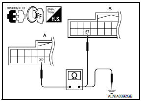
- Turn ignition switch OFF.
- Disconnect display unit connector M141 and AV control unit connector M154.
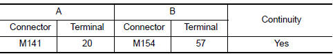
- Check continuity between display unit harness connector M141 (A) terminal 20 and AV control unit harness connector M154 (B) terminal 57.
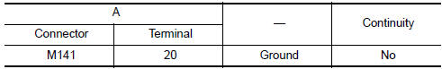
- Check continuity between display unit harness connector M141 (A) terminal 20 and ground.
2.CHECK VERTICAL SYNCHRONIZING (VP) SIGNAL
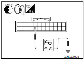
- Connect display unit connector M141 and AV control unit connector M154.
- Turn ignition switch ON.
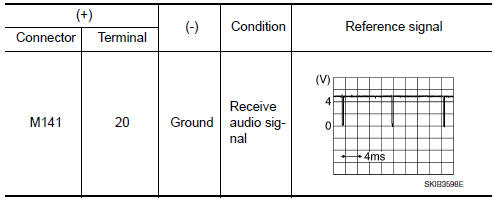
- Check signal between display unit harness connector M141 terminal 20 and ground.
 Horizontal synchronizing (HP) signal circuit
Description
In composite image (AUX image, camera image), transmit the vertical
synchronizing (VP) signal and horizontal
synchronizing (HP) signal from display unit to AV control unit so as to
...
 Front door speaker
Description
The AV control unit sends audio signals to the BOSE speaker amp. The BOSE
speaker amp. amplifies the
audio signals before sending them to the front door speakers using the audio
sig ...
Other materials:
U1000 CAN comm circuit
Description
CAN (Controller Area Network) is a serial communication line for real time
application. It is an on-vehicle multiplex
communication line with high data communication speed and excellent error
detection ability. Many electronic
control units are equipped onto a vehicle and each c ...
ECU diagnosis information
A/C AUTO AMP.
Reference Value
VALUES ON THE DIAGNOSIS TOOL
CONSULT MONITOR ITEM
A/C AUTO AMP. HARNESS CONNECTOR TERMINAL LAYOUT
TERMINALS AND REFERENCE VALUES FOR A/C AUTO AMP.
DTC Inspection Priority Chart
If some DTCs are displayed at the same time, perform inspections one b ...
Speedometer and odometer
This vehicle is equipped with a speedometer and
odometer. The speedometer is located on the
right side of the meter cluster. The odometer is
located within the vehicle information display.
Speedometer
The speedometer indicates vehicle speed.
Odometer/Twin trip odometer
The odometer and ...
Nissan Maxima Owners Manual
- Illustrated table of contents
- Safety-Seats, seat belts and supplemental restraint system
- Instruments and controls
- Pre-driving checks and adjustments
- Monitor, climate, audio, phone and voice recognition systems
- Starting and driving
- In case of emergency
- Appearance and care
- Do-it-yourself
- Maintenance and schedules
- Technical and consumer information
Nissan Maxima Service and Repair Manual

0.0056