Nissan Maxima Service and Repair Manual: Front drive shaft
Removal and Installation (LH)
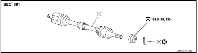
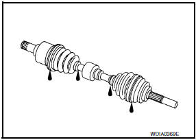
- Drive shaft
- Cotter pin
REMOVAL
- Remove wheel and tire using power tool. Refer to WT-60, "Adjustment".
- Remove wheel sensor from steering knuckle. Refer to BRC-102,
"Removal and Installation - Front Wheel Sensor".
CAUTION: Do not pull on wheel sensor harness.
- Remove brake hose lock plate from strut assembly.
- Remove brake caliper torque member bolts using power tool leaving
brake hose attached, then remove disc rotor. Reposition caliper aside
with wire. Refer to BR-32, "Removal and Installation of Brake Caliper and
Rotor".
NOTE: Avoid depressing brake pedal while brake caliper is removed.
- Remove cotter pin, then loosen lock nut from drive shaft using power tool.
- . Remove lower strut bolts and nuts using power tool. Refer to FSU-13, "Exploded View".
- Using a piece of wood and a hammer, tap on lock nut to disengage drive shaft from wheel hub.
CAUTION:
- Do not place drive shaft joint at an extreme angle. Also be careful not to overextend slide joint.
- Do not allow drive shaft to hang down without support.
NOTE: Use suitable puller if drive shaft cannot be separated from wheel hub and bearing assembly.
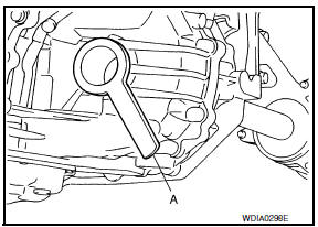
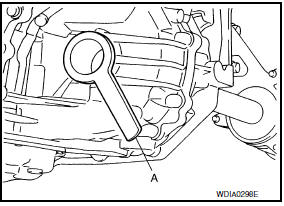
- Remove drive shaft from transaxle assembly.
- Use Tool (A) and sliding hammer (B) while inserting tip of tool between housing and transaxle assembly.
CAUTION: Do not place drive shaft joint at an extreme angle when removing drive shaft. Also be careful not to overextend slide joint.
Tool number (A) : KV40107500 ( - )
INSPECTION AFTER REMO
- Move joint up/down, left/right, and in axial direction. Check for any rough movement or significant looseness.
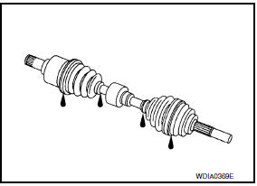
- Check boot for cracks or other damage, and for grease leakage.
- If damaged, disassemble drive shaft to verify damage, and repair or replace as necessary.
INSTALLATION
Installation is in the reverse order of removal. Note the following:
CAUTION: Do not reuse cotter pin.
- Install new circlip on drive shaft in the circular clip groove on
transaxle side. Refer to FAX-13, "Disassembly and Assembly (LH)".
CAUTION: Make sure the new circlip on the drive shaft is securely fastened. - In order to prevent damage to differential side oil seal, place Tool (A) onto oil seal before inserting drive shaft as shown. Slide drive shaft into slide joint and tap with a hammer to install securely.
Tool number (A) : KV38107900 ( - )
CAUTION: Make sure that circlip is completely engaged.
INSPECTION AFTER INSTALLATION
- Check wheel alignment. Refer to FSU-6, "Inspection and Adjustment".
- Adjust neutral position of steering angle sensor. Refer to BRC-6, "ADJUSTMENT OF STEERING ANGLE SENSOR NEUTRAL POSITION : Special Repair Requirement".
Removal and Installation (RH)
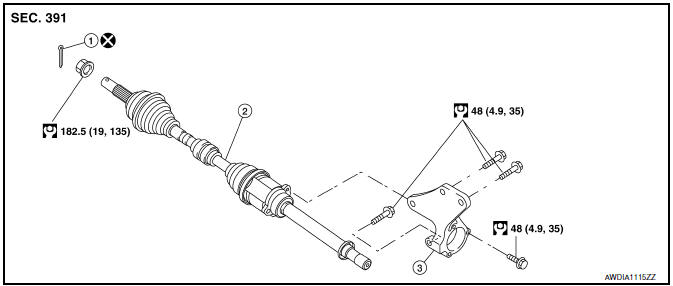
- Cotter pin
- Drive shaft
- Support bearing bracket
REMOVAL
- Remove wheel and tire using power tool. Refer to WT-60, "Adjustment".
- Remove wheel sensor from steering knuckle. Refer to BRC-102,
"Removal and Installation - Front Wheel Sensor".
CAUTION: Do not pull on wheel sensor harness. - Remove brake hose lock plate from strut assembly.
- Remove brake caliper torque member bolts using power tool leaving
brake hose attached, then remove disc rotor. Reposition caliper aside
with wire. Refer to BR-32, "Removal and Installation of Brake Caliper and
Rotor".
NOTE: Avoid depressing brake pedal while brake caliper is removed. - Remove cotter pin, then loosen lock nut from drive shaft using power tool.
- Remove lower strut bolts and nuts using power tool. Refer to FSU-13, "Exploded View".
- Using a piece of wood and a hammer, tap on lock nut to disengage drive shaft from wheel hub.
CAUTION:
- Do not place drive shaft joint at an extreme angle. Also be careful not to overextend slide joint.
- Do not allow drive shaft to hang down without support.
NOTE: Use suitable puller if drive shaft cannot be separated from wheel hub and bearing assembly.
- Remove bearing housing to support bearing bracket bolts.
- Remove drive shaft from transaxle assembly.
- Use Tool (A) and sliding hammer (B) while inserting tip of tool between housing and transaxle assembly.
CAUTION: Do not place drive shaft joint at an extreme angle when removing drive shaft. Also be careful not to overextend slide joint.
Tool number (A) : KV40107500 ( - )
- If necessary, remove the support bearing bracket.
- Remove front exhaust tube. Refer to EX-5, "Removal and Installation".
INSPECTION AFTER REMOVAL
- Move joint up/down, left/right, and in axial direction. Check for any rough movement or significant looseness.
- Check boot for cracks or other damage, and for grease leakage.
- If damaged, disassemble drive shaft to verify damage, and repair or replace as necessary
INSTALLATION
Installation is in the reverse order of removal. Note the following:
CAUTION: Do not reuse cotter pin.
- Install new circlip on drive shaft in the circular clip groove on transaxle side. Refer to FAX-19, "Disassembly and Assembly (RH)".
CAUTION: Make sure the new circlip on the drive shaft is securely fastened.
- In order to prevent damage to differential side oil seal, place Tool (A) onto oil seal before inserting drive shaft as shown. Slide drive shaft into slide joint and tap with a hammer to install securely.
Tool number (A) : KV38107900 ( - )
CAUTION: Make sure that circlip is completely engaged.
- When installing support bearing bracket, hand tighten the bolts, then tighten to specified torque.
INSPECTION AFTER INSTALLATION
- Check wheel alignment. Refer to FSU-6, "Inspection and Adjustment".
- Adjust neutral position of steering angle sensor. Refer to BRC-6, "ADJUSTMENT OF STEERING ANGLE SENSOR NEUTRAL POSITION : Special Repair Requirement".
 Front wheel hub
Removal and Installation
Steering knuckle
Splash guard
Wheel hub and bearing assembly
Cotter pin
REMOVAL
Remove wheel and tire using power tool. Refer to ...
 Unit disassembly and assembly
FRONT DRIVE SHAFT
Disassembly and Assembly (LH)
Circlip
Dust shield
Housing
Snap ring
Spider assembly
Stopper ring
Boot band
Boot
Shaft
D ...
Other materials:
Parking, license plate and tail lamps
System Diagram
System Description
BCM (Body Control Module) controls parking, license plate and tail lamps
operation.
IPDM E/R (Intelligent Power Distribution Module Engine Room) operates
parking, license plate and tail lamps according to CAN communication
signals from BCM.
Comp ...
Opening the fuel-filler door
The fuel-filler door automatically unlocks when
the driver's door is unlocked.
1. Unlock the fuel-filler door using one of the
following operations.
Unlock the driver's door with the Intelligent
Key.
Push the power door lock switch to the
unlock position.
Push the door handle re ...
Auto light system
System Diagram
System Description
BCM (Body Control Module) controls auto light operation according to
signals from optical sensor, lighting switch and ignition switch.
IPDM E/R (Intelligent Power Distribution Module Engine Room) operates
parking, license plate, tail, front fog lamps ...
Nissan Maxima Owners Manual
- Illustrated table of contents
- Safety-Seats, seat belts and supplemental restraint system
- Instruments and controls
- Pre-driving checks and adjustments
- Monitor, climate, audio, phone and voice recognition systems
- Starting and driving
- In case of emergency
- Appearance and care
- Do-it-yourself
- Maintenance and schedules
- Technical and consumer information
Nissan Maxima Service and Repair Manual

0.0058