Nissan Maxima Service and Repair Manual: Unit disassembly and assembly
FRONT DRIVE SHAFT
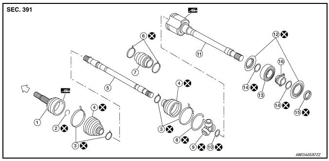
Disassembly and Assembly (LH)
- Circlip
- Dust shield
- Housing
- Snap ring
- Spider assembly
- Stopper ring
- Boot band
- Boot
- Shaft
- Damper band
- Dynamic damper
- Circlip
- . Joint sub-assembly
 : Wheel side
 : Fill using NISSAN Genuine grease or
equivalent.
: Fill using NISSAN Genuine grease or
equivalent.
DISASSEMBLY
Transaxle Side
- Mount front drive shaft in a vise.
CAUTION: When mounting shaft in a vise, always use copper or aluminum plates between vise and shaft. - Remove boot bands and slide the boot back.
- Remove circlip and dust shield from slide joint housing.
- Put matching marks on slide joint housing and shaft before separating slide joint assembly.
- Remove stopper ring with a suitable tool, then pull out slide joint housing.
- Put matching marks on spider assembly and shaft.
- Remove snap ring using a suitable tool, then remove spider assembly from shaft.
- Remove boot from shaft.
- Clean the old grease off of the slide joint assembly.
Wheel Side
- Mount the front drive shaft in a vise.
CAUTION: When mounting shaft in a vise, always use copper or aluminum plates between vise and shaft.
- Remove boot bands and slide the boot back.
- Screw a sliding hammer or suitable tool 30 mm (1.18 in) or more into threaded part of joint sub-assembly. Pull joint sub-assembly out of shaft.
CAUTION:
- Align sliding hammer or suitable tool and drive shaft then remove joint sub-assembly by pulling directly.
- If joint sub-assembly cannot be removed after five or more unsuccessful attempts, replace the entire drive shaft assembly.
- Remove boot from shaft.
- Remove circlip from shaft.
- While rotating ball cage, clean the old grease off of the joint sub-assembly.
Damper
- Remove damper bands, then remove damper from shaft.
INSPECTION AFTER DISASSEMBLY
Shaft
- Replace shaft if there is bending, cracking, or other damage.
Joint Sub-assembly
- Make sure there is no rough rotation or unusual axial looseness.
- Make sure there is no foreign material inside joint sub-assembly.
- Check joint sub-assembly for compression scars, cracks or fractures.
CAUTION: If there are any irregular conditions of joint sub-assembly components, replace the entire joint subassembly.
Slide Joint Housing
- Make sure there are no compression scars, cracks or fractures or unusual wear of ball rolling surface.
- Make sure there is no damage to shaft screws.
- Make sure there is no deformation of boot installation parts.
Ball Cage
- Make sure there are no compression scars, cracks, fractures of sliding surface.
Steel Ball
- Make sure there are no compression scars, cracks, fractures or unusual wear.
Inner Race
- Check ball sliding surface for compression scars, cracks or fractures.
- Make sure there is no damage to serrated part.
CAUTION: If there are any irregular conditions in the component, replace with a new set of joint sub-assembly, ball cage, steel ball and inner race.
Damper
- Check damper for cracks or wear. Install damper with new damper bands.
ASSEMBLY
Transaxle Side
- Install new boot and new small boot band on shaft.
CAUTION:
- Cover drive shaft serration with tape to prevent damage to boot during installation.
- Do not reuse boot band and boot.
- Remove protective tape wound around serrated part of shaft.

- Install spider assembly securely, making sure the matching marks which were made during disassembly are properly aligned.
- Install new snap ring using a suitable tool.
CAUTION: Do not reuse snap ring. - Pack drive shaft with specified amount of new grease (Genuine NISSAN Grease or equivalent).
- Install new stopper ring to housing of slide joint assembly.
CAUTION: Do not reuse stopper ring. - After installation, pull shaft to check engagement between slide joint assembly and stopper ring.
- Install boot securely into grooves (indicated by * marks) as shown.
CAUTION:
- - If there is grease on boot mounting surfaces (indicated by * marks) of shaft and housing, boot may come off. Clean all grease from surfaces.
- - Do not reuse boot.
- Make sure boot installation length (L) is the length specified below. Insert a suitable tool into the large end of boot. Bleed air from boot to prevent boot deformation.
CAUTION:
- Boot may break if boot installation length is less than standard value.
- Be careful that the tool does not contact inside surface of boot.
- Secure large end of boot with new boot band as shown.
- Put boot band in groove of drive shaft boot. Then insert pawls into holes.
CAUTION: Do not reuse boot bands.
NOTE: Insert projection (A) and guide slit (B).
 : Pawl
- Pinch projection on boot band with suitable pliers to tighten band.
- Insert tip of band below end of pawl.

 : Pawl
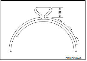
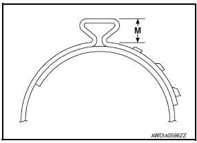
- Install new small boot band securely using Tool.
Tool number : KV40107300 ( - )
CAUTION:
- Do not reuse boot bands.
- Secure boot band so that dimension (M) meets specification as shown.
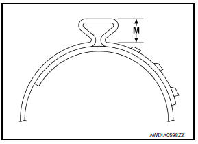
Dimension (M) : Refer to FAX-27, "Boot Bands".
- Install new dust shield to slide joint housing.
CAUTION: Do not reuse dust shield. - After installing housing and shaft, make sure boot position is correct. If boot position is not correct, remove old boot bands then reposition the boot and secure with new boot bands.
Wheel Side
- Add grease (Genuine NISSAN Grease or equivalent) into joint sub-assembly serration hole until grease begins to ooze from ball groove and serration hole. After inserting grease, use a shop cloth to wipe off old grease that has oozed out.
- Cover serrated part of shaft with tape. Install new boot band and
boot to shaft. Be careful not to damage boot.
CAUTION: Do not reuse boot band and boot. - Remove protective tape wound around serrated part of shaft.
- Attach new circlip to shaft. The circlip must fit securely into shaft
groove. Attach nut to joint sub-assembly.
Use a suitable tool to press-fit.
CAUTION: Do not reuse circlip.
- Insert the amount of new grease (Genuine NISSAN Grease or equivalent) listed below into housing from large end of boot.
- Install boot securely into grooves (indicated by * marks) as shown.
CAUTION:
- If there is grease on boot mounting surfaces (indicated by
* marks) of shaft and housing, boot may come off.
Remove all grease from surfaces.
- Do not reuse boot.
- Make sure boot installation length (L) is the specified length
indicated below. Insert a suitable tool into the large end of boot.
Bleed air from boot to prevent boot deformation.
Boot installation length (L) : Refer to FAX-26, "Drive Shaft".
CAUTION:
- Boot may break if boot installation length is less than standard value.
- Be careful that the tool does not contact inside surface of boot.
- Install new large and small boot bands securely using Tool.
Tool number : KV40107300 ( - )
CAUTION:
- Do not reuse boot bands.
- Secure boot band so that dimension (M) meets specification as shown.
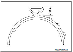
Dimension (M) : Refer to FAX-27, "Boot Bands".
- After installing housing and shaft, rotate boot to check whether or not the actual position is correct. If boot position is not correct, remove old boot bands then reposition the boot and secure with new boot bands.
Damper
- Use new damper bands for installation.
CAUTION: Do not reuse damper bands. - Install damper from stationary-joint side while holding it securely.
(A) : Refer to FAX-26, "Dynamic Damper".
(B) : Refer to FAX-26, "Dynamic
Damper".
Disassembly and Assembly (RH)
- Joint sub-assembly
- Circlip
- Boot band
- Boot
- Shaft
- Damper band
- Dynamic damper
- Stopper ring
- Spider assembly
- Snap ring
- Housing
- Dust shield
- Support bearing
- Snap ring
- Dust shield
- Bearing housing
 : Wheel side
 : Fill using NISSAN Genuine grease or
equivalent.
: Fill using NISSAN Genuine grease or
equivalent.
DISASSEMBLY
Transaxle Side
- Press shaft in a vise.
CAUTION: When retaining shaft in a vise, always use copper or aluminum plates between vise and shaft. - Remove circlip and dust shield from slide joint housing.
- Remove boot bands and slide the boot back.
- Put matching marks on slide joint housing and shaft before separating slide joint housing.
- Remove stopper ring using a suitable tool, then pull out slide joint housing.
- Put matching marks on spider assembly and shaft.
- Remove snap ring using a suitable tool, then remove spider assembly from shaft.
- Remove boot from shaft.
- Clean old grease off of the slide joint housing.
Wheel Side
- Mount the front drive shaft in a vise.
CAUTION: When mounting shaft in a vise, always use copper or aluminum plates between vise and shaft. - Remove boot bands and slide the boot back.
- Screw a sliding hammer or suitable tool 30 mm (1.18 in) or more into threaded part of joint sub-assembly. Pull joint sub-assembly out of shaft.
CAUTION:
- Align sliding hammer or suitable tool and drive shaft then remove joint sub-assembly by pulling directly.
- If joint sub-assembly cannot be removed after five or more unsuccessful attempts, replace the entire drive shaft assembly.
- Remove boot from shaft.
- Remove circlip from shaft.
Support Bearing
- Remove dust shields from slide joint assembly using a suitable tool.
- Remove snap ring using a suitable tool.
- Press support bearing assembly off slide joint assembly using a suitable tool.
- Separate support bearing from bracket using a suitabe tool.
Damper
- Remove damper bands, then remove damper from shaft.
INSPECTION AFTER DISASSEMBLY
Shaft
- Replace shaft if there is any bending, cracking, or other damage.
Joint Sub-assembly
- Make sure there is no rough rotation or unusual axial looseness.
- Make sure there is no foreign material inside joint sub-assembly.
- Check joint sub-assembly for compression scars, cracks or fractures.
CAUTION: If there are any irregular conditions of joint sub-assembly components, replace the entire joint subassembly.
Sliding Joint Housing and Spider Assembly
- If roller surface of spider assembly has scratches or wear, replace housing and spider assembly.
NOTE: Housing and spider assembly are components which are used as a set.
Support Bearing
- Make sure wheel bearing rolls freely and is free from noise, cracks, pitting or wear.
Damper
- Check damper for cracks or wear. Install damper with new damper bands
ASSEMBLY
Transaxle Side
- Cover serrated part of shaft with tape. Install new boot and boot
band onto shaft. Be careful not to damage boot.
CAUTION: Do not reuse boot band and boot. - Remove protective tape wound around serrated part of shaft.
- Install spider assembly securely, making sure the matching marks which were made during disassembly are properly aligned.
- Install new snap ring using a suitable tool.
CAUTION: Do not reuse snap ring. - Pack drive shaft with specified amount of grease (Genuine NISSAN Grease or equivalent).
Grease quantity : Refer to FAX-26, "Drive Shaft".
- Install new stopper ring to slide joint assembly. CAUTION: Do not reuse stopper ring.
- After installation, pull shaft to check engagement between slide joint assembly and stopper ring.
- Install boot securely into grooves (indicated by * marks) as shown.
CAUTION:
- - If there is grease on boot mounting surfaces (indicated by *
marks) of shaft and housing, boot may come off.
Remove all grease from surfaces.
- Do not reuse boot.
- Make sure boot installation length (L) is the length indicated below. Insert a suitable tool into the large end of boot. Bleed air from boot to prevent boot deformation.
Boot installation length (L) : Refer to FAX-26, "Drive Shaft".
CAUTION:
- Boot may break if boot installation length is less than standard value.
- Be careful that the tool does not contact inside surface of boot.
- Secure large end of boot with new boot band as shown.
- Put boot band in groove of drive shaft boot. Then insert pawls into holes.
CAUTION: Do not reuse boot bands.
NOTE: Insert projection (A) and guide slit (B).
 : Pawl
- Pinch projection on boot band with suitable pliers to tighten band.
- Insert tip of band below end of pawl.
 : Pawl
- Install new small boot band securely using Tool.
Tool number : KV40107300 ( - )
CAUTION:
- - Do not reuse boot bands.
- Secure boot band so that dimension (M) meets specification as shown.
Dimension (M) : Refer to FAX-27, "Boot Bands"
- Install new dust shield to slide joint housing. CAUTION: Do not reuse dust shield.
- After installing housing and shaft, rotate boot to check whether or not the actual position is correct. If boot position is not correct, remove old boot bands then reposition the boot and secure with new boot bands.
Wheel Side
- Add grease (Genuine NISSAN Grease or equivalent) into joint sub-assembly serration hole until grease begins to ooze from ball groove and serration hole. After inserting grease, use a shop cloth to wipe off old grease that has oozed out.
- Cover serrated part of shaft with tape. Install new boot and boot
band onto shaft. Be careful not to damage boot.
CAUTION: Do not reuse boot band and boot. - Remove protective tape wound around serrated part of shaft.
- Attach new circlip to shaft. The circlip must fit securely into shaft
groove. Attach nut to joint sub-assembly.
Use a suitable tool to press-fit.
CAUTION: Do not reuse circlip. - Insert the amount of new grease (Genuine NISSAN Grease or equivalent) listed below into housing from large end of boot.
Grease quantity : Refer to FAX-26, "Drive Shaft".
- Install boot securely into grooves (indicated by * marks) as shown.
CAUTION:
- If there is grease on boot mounting surfaces (indicated by
* marks) of shaft and housing, boot may come off.
Remove all grease from surfaces.
- Do not reuse boot.
- Make sure boot installation length (L) is the specified length,
indicated below. Insert a suitable tool into the large end of boot.
Bleed air from boot to prevent boot deformation.
Boot installation length (L) : Refer to FAX-26, "Drive Shaft".
CAUTION:
- Boot may break if boot installation length is less than standard value.
- Be careful that the tool does not contact inside surface of boot.
- Install new large and small boot bands securely using Tool.
Tool number : KV40107300 ( -
CAUTION:
- - Do not reuse boot bands.
- Secure boot band so that dimension (M) meets specification as shown.
Dimension (M) : Refer to FAX-27, "Boot Bands".
- After installing housing and shaft, rotate boot to check whether or not the actual position is correct. If boot position is not correct, remove old boot bands then reposition the boot and secure with new boot band
Damper
- Use new damper bands for installation. CAUTION: Do not reuse damper bands.
- Install damper from stationary-joint side while holding it securely.
(A) : Refer to FAX-26, "Dynamic Damper".
(B) : Refer to FAX-26, "Dynamic
Damper".
 Front drive shaft
Removal and Installation (LH)
Drive shaft
Cotter pin
REMOVAL
Remove wheel and tire using power tool. Refer to WT-60, "Adjustment".
Remove wheel sensor from steering knu ...
 Service data and specifications (SDS)
Wheel Bearing
Drive Shaft
*: Boot installation grooves
Dynamic Damper
NOTE: Measured from wheel side
Boot Bands
...
Other materials:
Front combination lamp
Disassembly and Assembly
EXPLODED VIEW
Front combination lamp
Halogen bulb (low beam)
Halogen bulb socket (low beam)
Side marker lamp bulb
Side marker lamp socket
Front turn signal lamp socket
Front turn signal lamp bulb
Halogen bulb socket (high beam)
Halogen bulb (high ...
How to enable/disable the BSW system
Perform the following steps to enable or disable
the BSW system.
1. Press the button until
"Settings" displays
in the vehicle information display and
then press OK. Use the button
to
select "Driver Assistance". Then press the
OK button.
2. Select "Blind Spot" and press the ...
Front bumper
Exploded View
Tow cover
Engine under cover
Core support cover
Fog lamp cover
Fog lamp (if equipped)
Front bumper fascia
Center support bracket
Upper fascia support
Front bumper upper bracket
Front bumper side bracket
Front bumper fascia seal
Front bumper stiffener ...
Nissan Maxima Owners Manual
- Illustrated table of contents
- Safety-Seats, seat belts and supplemental restraint system
- Instruments and controls
- Pre-driving checks and adjustments
- Monitor, climate, audio, phone and voice recognition systems
- Starting and driving
- In case of emergency
- Appearance and care
- Do-it-yourself
- Maintenance and schedules
- Technical and consumer information
Nissan Maxima Service and Repair Manual

0.0065