Nissan Maxima Service and Repair Manual: Fender protector
Exploded View
Front
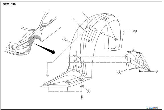
- Front fender protector
- Front fender protector side cover
- J-clip
Rear
- Rear wind deflector
- Rear fender protector
Removal and Installation
FRONT FENDER PROTECTOR
Removal
NOTE: Position front tires as necessary to remove the front fender protectors.
- Remove the front screw from center mudguard.
- Remove the front fender protector side cover clips, then remove front fender protector side cover.
- Remove the front fender protector screws and clips, then remove front fender protector.
Installation
Installation is in the reverse order of removal.
NOTE: Position front tires as necessary to install the front fender protectors.
REAR FENDER PROTECTOR
Removal
- Remove the rear tire/wheel assembly. Refer to WT-60, "Adjustment".
- Remove the rear fender protector screws and clips.
- Remove the fender protector.
- Remove the wind deflector screws, then remove the wind deflector.
Installation
Installation is in the reverse order of removal.
 Cowl top
Exploded View
Cowl top side trim cover (RH)
Cowl top grille
Lower cowl top extension brace
Lower cowl top extension (RH)
Lower cowl top extension seal (RH)
Lower cowl top extension ...
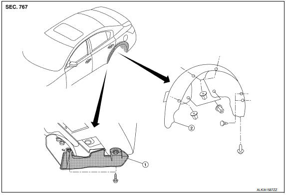
 Mudguard
Exploded View
Mudguard
Clip C205
Clip CF118
Front
Removal and Installation
REMOVAL
Remove the clips located on the underbody.
Remove the center mudguard front and rear screws ...
Other materials:
Ground
Ground Distribution
MAIN HARNESS
ENGINE ROOM HARNESS
FRONT END MODULE HARNESS
ENGINE CONTROL HARNESS
BODY HARNESS
BODY NO. 2 HARNESS
...
AV control unit
Reference Value
VALUES ON THE DIAGNOSIS TOOL
CONSULT data monitor item
TERMINAL LAYOUT
PHYSICAL VALUES
*1 With satellite radio
DTC Index
Self-diagnosis results display item
...
Emission Control System Maintenance
Drive belts*:
Check engine drive belts for wear, fraying or
cracking and for proper tension. Replace any
damaged drive belts.
Engine air filter:
Replace at specified intervals. When driving for
prolonged periods in dusty conditions,
check/replace the filter more frequently.
Engine coolant*:
...
Nissan Maxima Owners Manual
- Illustrated table of contents
- Safety-Seats, seat belts and supplemental restraint system
- Instruments and controls
- Pre-driving checks and adjustments
- Monitor, climate, audio, phone and voice recognition systems
- Starting and driving
- In case of emergency
- Appearance and care
- Do-it-yourself
- Maintenance and schedules
- Technical and consumer information
Nissan Maxima Service and Repair Manual

0.0075