Nissan Maxima Service and Repair Manual: Cowl top
Exploded View
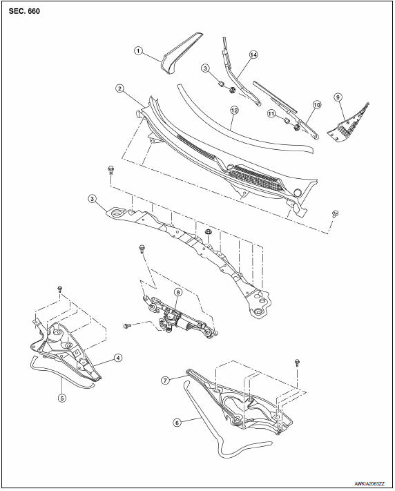
- Cowl top side trim cover (RH)
- Cowl top grille
- Lower cowl top extension brace
- Lower cowl top extension (RH)
- Lower cowl top extension seal (RH)
- Lower cowl top extension seal (LH)
- Lower cowl top extension (LH)
- Front wiper drive assembly
- Cowl top side trim cover (LH)
- Wiper arm and blade assembly (LH)
- Wiper arm cap (LH)
- Cowl top weatherstrip
- Wiper arm cap (RH)
- Wiper arm and blade assembly (RH)
Removal and Installation
REMOVAL
- Remove both wiper arms (RH/LH). Refer to WW-78, "FRONT WIPER ARMS : Removal and Installation".
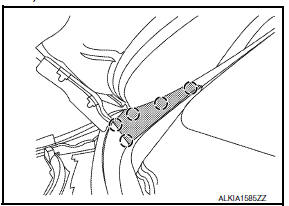
- Remove the cowl top weatherstrip clips, then remove cowl top weatherstrip.
- Release the pawls, then remove the cowl top side trim covers (RH/LH).
 : Pawl
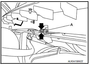
- Pinch the cowl top extension clips (A) to release, then remove.
: Front - Disconnect the washer nozzle supply hose.
- Release the cowl top grille clips, then remove cowl top.
- Disconnect the harness connector from the wiper motor. Refer to WW-78, "FRONT WIPER DRIVE ASSEMBLY : Removal and Installation".
- Remove the lower cowl top extension brace bolts, then remove the lower cowl extension brace.
- Remove the front wiper drive assembly. Refer to WW-78, "FRONT WIPER DRIVE ASSEMBLY : Removal and Installation".
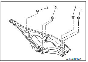
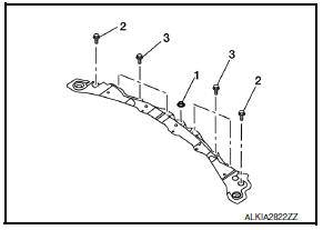
- Remove the lower cowl top extension RH/LH bolts, then remove lower cowl top extensions (RH/LH).
INSTALLATION
Installation is in the reverse order of removal.
CAUTION: After installing, perform adjustment of wiper arm. Refer to WW-78, "FRONT WIPER ARMS : Removal and Installation".
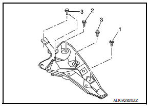
- When installing the lower cowl top extension RH, tighten the bolts in the order shown.
- When installing the lower cowl top extension LH, tighten the bolts in the order shown.
- When installing the lower cowl top extension brace, tighten the bolts in the order shown.
 Front grille
Removal and Installation
Core support cover
Front grille Pawl
REMOVAL
Remove the core support cover clips, then remove core support
cover.
Release the front air guide clips, t ...
 Fender protector
Exploded View
Front
Front fender protector
Front fender protector side cover
J-clip
Rear
Rear wind deflector
Rear fender protector
Removal and Installation
FRONT FEN ...
Other materials:
ECU diagnosis information
POWER STEERING CONTROL UNIT
Reference Value
TERMINA LAYOUT
PHYSICAL VALUES
CAUTION: When using circuit tester or oscilloscope to
measure voltage for inspection, be sure not to extend forcibly any connector
terminals.
Fail Saf
EPS system
EPS system enters the fail-safe mode (that al ...
Windows
Power windows
WARNING
Make sure that all passengers have
their hands, etc. inside the vehicle while
it is in motion and before closing the
windows. Use the window lock switch to
prevent unexpected use of the power
windows.
To help avoid risk of injury or death
through unintended o ...
Audio
Some of the information and operations available
on the control panel can also be viewed and
operated on the vehicle information display. The
vehicle information display operations can be
conducted with the switches on the steering
wheel.
Use or
and select
on the vehicle
information disp ...
Nissan Maxima Owners Manual
- Illustrated table of contents
- Safety-Seats, seat belts and supplemental restraint system
- Instruments and controls
- Pre-driving checks and adjustments
- Monitor, climate, audio, phone and voice recognition systems
- Starting and driving
- In case of emergency
- Appearance and care
- Do-it-yourself
- Maintenance and schedules
- Technical and consumer information
Nissan Maxima Service and Repair Manual

0.0057