Nissan Maxima Service and Repair Manual: Front wheel hub
Removal and Installation
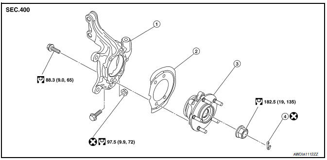
- Steering knuckle
- Splash guard
- Wheel hub and bearing assembly
- Cotter pin
REMOVAL
- Remove wheel and tire using power tool. Refer to WT-60, "Adjustment".
- Remove wheel sensor from steering knuckle. Refer to BRC-102,
"Removal and Installation - Front Wheel Sensor".
CAUTION: Do not pull on wheel sensor harness. - Remove brake hose lock plate from strut assembly.
- Remove brake caliper torque member bolts using power tool leaving
brake hose attached, then remove disc rotor. Reposition caliper aside
with wire. Refer to BR-32, "Removal and Installation of Brake Caliper and
Rotor".
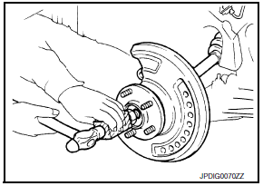
NOTE: Avoid depressing brake pedal while brake caliper is removed. - Remove cotter pin, then loosen lock nut from drive shaft using power tool.
- Using a piece of wood and a hammer, tap on lock nut to disengage drive shaft from wheel hub.
CAUTION:
- Do not place drive shaft joint at an extreme angle. Also be careful not to overextend slide joint.
- Do not allow drive shaft to hang down without support.
NOTE: Use suitable puller if drive shaft cannot be separated from wheel hub and bearing assembly.
- Remove wheel hub and bearing assembly bolts using power tool.
- Remove splash guard and wheel hub and bearing assembly from steering knuckle.
INSPECTION AFTER REMOVAL
Check for deformity, cracks and damage on each part, replace if necessa
INSTALLATION
Installation is in the reverse order of removal.
CAUTION:
- Do not reuse cotter pin.
- Do not reuse wheel hub lock nut.
- When installing wheel hub and bearing assembly to steering knuckle, align cutout in toner ring cover with wheel sensor mounting hole in steering knuckle.

 Front drive shaft
Removal and Installation (LH)
Drive shaft
Cotter pin
REMOVAL
Remove wheel and tire using power tool. Refer to WT-60, "Adjustment".
Remove wheel sensor from steering knu ...
Other materials:
Main line between HVAC and A-bag circuit
Diagnosis Procedure
1.CHECK HARNESS CONTINUITY (OPEN CIRCUIT)
Turn the ignition switch OFF.
Disconnect the battery cable from the negative terminal.
Disconnect the following harness connectors.
A/C auto amp.
Harness connectors M1 and E30
Check the continuity between the A/C au ...
Readiness for inspection/maintenance (I/M) test
Due to legal requirements in some states and
Canadian Provinces, your vehicle may be required
to be in what is called the "ready condition"
for an Inspection/Maintenance (I/M) test of
the emission control system.
The vehicle is set to the "ready condition" when it
is driven through certain d ...
Power seat for passenger side
Wiring Diagram
...
Nissan Maxima Owners Manual
- Illustrated table of contents
- Safety-Seats, seat belts and supplemental restraint system
- Instruments and controls
- Pre-driving checks and adjustments
- Monitor, climate, audio, phone and voice recognition systems
- Starting and driving
- In case of emergency
- Appearance and care
- Do-it-yourself
- Maintenance and schedules
- Technical and consumer information
Nissan Maxima Service and Repair Manual

0.0061