Nissan Maxima Service and Repair Manual: Horizontal synchronizing (HP) signal circuit
Description
In composite image (AUX image, camera image), transmit the vertical synchronizing (VP) signal and horizontal synchronizing (HP) signal from display unit to AV control unit so as to synchronize the RGB images displayed with AV control unit such as the image quality adjusting menu, etc.
Diagnosis Procedure
1.CHECK CONTINUITY HORIZONTAL SYNCHRONIZING (HP) SIGNAL CIRCUIT
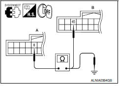
- Turn ignition switch OFF.
- Disconnect display unit connector M141 and AV control unit connector M117.
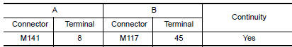
- Check continuity between display unit harness connector M141 (A) terminal 8 and AV control unit harness connector M117 (B) terminal 45.
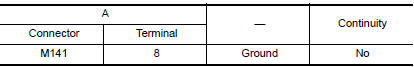
- Check continuity between display unit harness connector M141 (A) terminal 8 and ground.
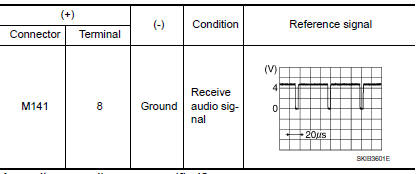
2.CHECK HORIZONTAL SYNCHRONIZING (HP) SIGNAL
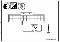
- Connect display unit connector M141 and AV control unit connector M117.
- Turn ignition switch ON.
- Check signal between display unit harness connector M141 terminal 8 and ground.
 RGB AREA (YS) signal circuit
Description
Transmits the display area of RGB image displayed by AV control unit with RGB
area (YS) signal to display unit.
Diagnosis Procedure
1.CHECK CONTINUITY RGB AREA (YS) SIGNAL CIRCUIT
...
 Vertical synchronizing (VP) signal circuit
Description
In composite image (AUX image, camera image), transmit the vertical
synchronizing (VP) signal and horizontal synchronizing (HP) signal from
display unit to AV control unit so as to sy ...
Other materials:
Precaution
PRECAUTIONS
Precaution for Supplemental Restraint System (SRS) "AIR BAG" and "SEAT
BELT
PRE-TENSIONER"
The Supplemental Restraint System such as "AIR BAG" and "SEAT BELT
PRE-TENSIONER", used along
with a front seat belt, helps to reduce the risk or severity of injury to t ...
STRG branch line circuit
Diagnosis Procedure
1.CHECK CONNECTOR
Turn the ignition switch OFF.
Disconnect the battery cable from the negative terminal.
Check the terminals and connectors of the steering angle sensor
for damage, bend and loose connection
(unit side and connector side).
2.CHECK HARNESS FOR OPE ...
Precaution
Precaution for Supplemental Restraint System (SRS) "AIR BAG" and
"SEAT BELT PRE-TENSIONER"
The Supplemental Restraint System such as "AIR BAG" and "SEAT BELT
PRE-TENSIONER", used along with a front seat belt, helps to reduce the risk
or severity of injury to the driver and front passenger for ...
Nissan Maxima Owners Manual
- Illustrated table of contents
- Safety-Seats, seat belts and supplemental restraint system
- Instruments and controls
- Pre-driving checks and adjustments
- Monitor, climate, audio, phone and voice recognition systems
- Starting and driving
- In case of emergency
- Appearance and care
- Do-it-yourself
- Maintenance and schedules
- Technical and consumer information
Nissan Maxima Service and Repair Manual

0.0057