Nissan Maxima Service and Repair Manual: Vertical synchronizing (VP) signal circuit
Description
In composite image (AUX image, camera image), transmit the vertical synchronizing (VP) signal and horizontal synchronizing (HP) signal from display unit to AV control unit so as to synchronize the RGB images displayed with AV control unit, such as the image quality adjusting menu, etc.
Diagnosis Procedure
1.CHECK CONTINUITY VERTICAL SYNCHRONIZING (VP) SIGNAL CIRCUIT
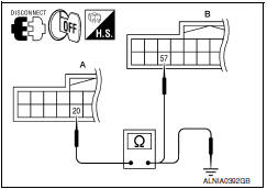
- Turn ignition switch OFF.
- Disconnect display unit connector M141 and AV control unit connector M117.
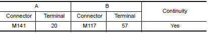
- Check continuity between display unit harness connector M141 (A) terminal 20 and AV control unit harness connector M117 (B) terminal 57.
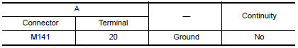
- Check continuity between display unit harness connector M141 (A) terminal 20 and ground
2.CHECK VERTICAL SYNCHRONIZING (VP) SIGNAL
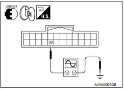
- Connect display unit connector M141 and AV control unit connector M117.
- Turn ignition switch ON.
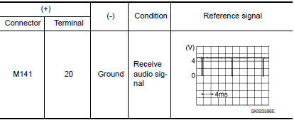
- Check signal between display unit harness connector M141 terminal 20 and ground.
 Horizontal synchronizing (HP) signal circuit
Description
In composite image (AUX image, camera image), transmit the vertical
synchronizing (VP) signal and horizontal synchronizing (HP) signal from
display unit to AV control unit so as to sy ...
 Front door speaker
Description
The AV control unit sends audio signals to the front door speakers using the
front door speaker circuits.
Diagnosis Procedure
1.CONNECTOR CHECK
Check the AV control unit and speaker ...
Other materials:
U1000 CAN comm circuit
Description
DTC Logic
DTC DETECTION LOGIC
NOTE:
U1000 can be set if a module harness was disconnected and reconnected, perhaps
during a repair. Confirm
that there are actual CAN diagnostic symptoms and a present DTC by performing
the Self Diagnostic Result
procedure.
Diagnosis Proc ...
Child safety
WARNING
Do not allow children to play with the seat
belts. Most seating positions are
equipped with Automatic Locking Retractor
(ALR) mode seat belts. If the seat belt
becomes wrapped around a child's neck
with the ALR mode activated, the child can
be seriously injured or killed if the seat
...
Passenger side door mirror defogger
Description
Heats the heating wire with the power supply from the rear window defogger
relay to prevent the door mirror
from fogging up.
Component Function Check
1.CHECK DOOR MIRROR DEFOGGER RH
Check that the heating wire of door mirror defogger RH is heated when turning
the rear window de ...
Nissan Maxima Owners Manual
- Illustrated table of contents
- Safety-Seats, seat belts and supplemental restraint system
- Instruments and controls
- Pre-driving checks and adjustments
- Monitor, climate, audio, phone and voice recognition systems
- Starting and driving
- In case of emergency
- Appearance and care
- Do-it-yourself
- Maintenance and schedules
- Technical and consumer information
Nissan Maxima Service and Repair Manual

0.0054