Nissan Maxima Service and Repair Manual: Front door speaker
Description
The AV control unit sends audio signals to the front door speakers using the front door speaker circuits.
Diagnosis Procedure
1.CONNECTOR CHECK
Check the AV control unit and speaker connectors for the following:
- Proper connection
- Damage
- Disconnected or loose terminals
2.HARNESS CHECK
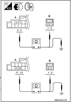
- Disconnect AV control unit connector M115 (A) and suspect speaker connector (B).
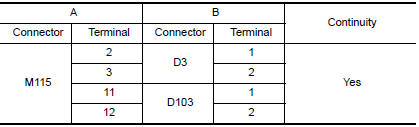
- Check continuity between AV control unit harness connector M115 (A) terminal and suspect speaker harness connector (B) terminal.
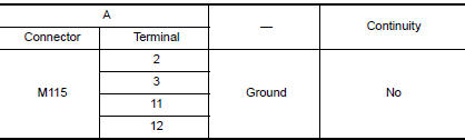
- Check continuity between AV control unit harness connector M115 (A) terminal and ground.
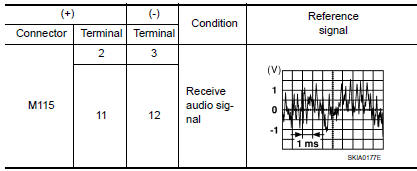
3.FRONT DOOR SPEAKER SIGNAL CHECK
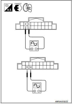
- Connect AV control unit connector and front speaker connector.
- Turn ignition switch to ACC.
- Push POWER switch.
- Check the signal between AV control unit harness connector terminals with CONSULT or oscilloscope.
 Vertical synchronizing (VP) signal circuit
Description
In composite image (AUX image, camera image), transmit the vertical
synchronizing (VP) signal and horizontal synchronizing (HP) signal from
display unit to AV control unit so as to sy ...
 Tweeter
Description
The AV control unit sends audio signals to the tweeters using the front door
speaker circuits.
Diagnosis Procedure
1.CONNECTOR CHECK
Check the AV control unit and speaker connectors ...
Other materials:
Steering switch
Removal and Installation
REMOVAL
Remove the driver airbag module. Refer to SR-12, "Removal and
Installation".
Remove the steering wheel audio control switch screws (A).
Release the steering wheel audio control switch harness clips (B).
Remove the steering wheel audio control switche ...
Evap leak check
Inspection
CAUTION:
Never use compressed air or a high pressure pump.
Never exceed 4.12 kPa (0.042 kg/cm2, 0.6 psi) of pressure in
EVAP system.
NOTE:
Do not start engine.
Improper installation of EVAP service port adapter (commercial
service tool) ...
P1610 lock mode
Description
Performs ID verification through BCM and Intelligent Key
when push-button ignition switch is pressed.
Prohibits the start of engine when an unregistered ID of Intelligent Key is
used.
DTC Logic
DTC DETECTION LOGIC
DTC CONFIRMATION PROCEDURE
1.PERFORM DTC CONFIRMATION PROCED ...
Nissan Maxima Owners Manual
- Illustrated table of contents
- Safety-Seats, seat belts and supplemental restraint system
- Instruments and controls
- Pre-driving checks and adjustments
- Monitor, climate, audio, phone and voice recognition systems
- Starting and driving
- In case of emergency
- Appearance and care
- Do-it-yourself
- Maintenance and schedules
- Technical and consumer information
Nissan Maxima Service and Repair Manual

0.0071