Nissan Maxima Service and Repair Manual: Wiring diagram
CHARGING SYSTEM
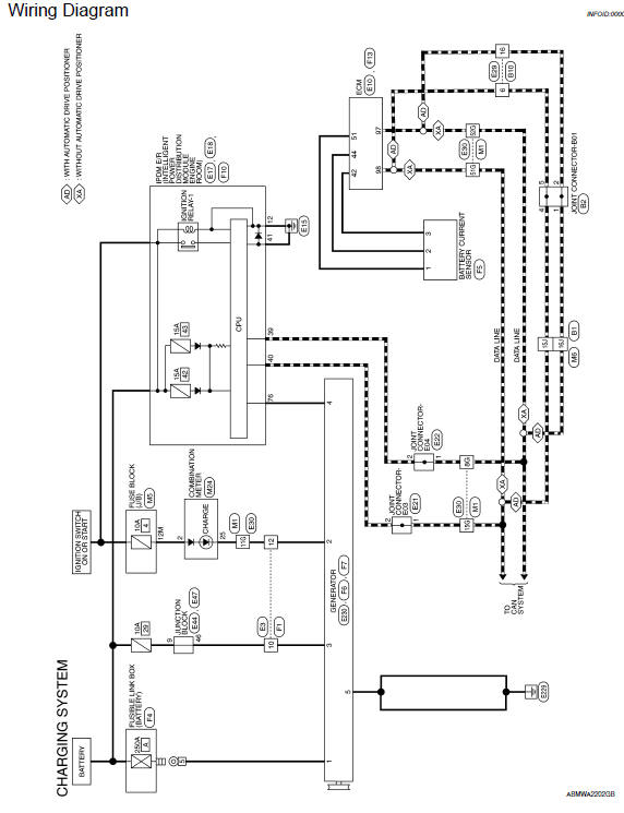
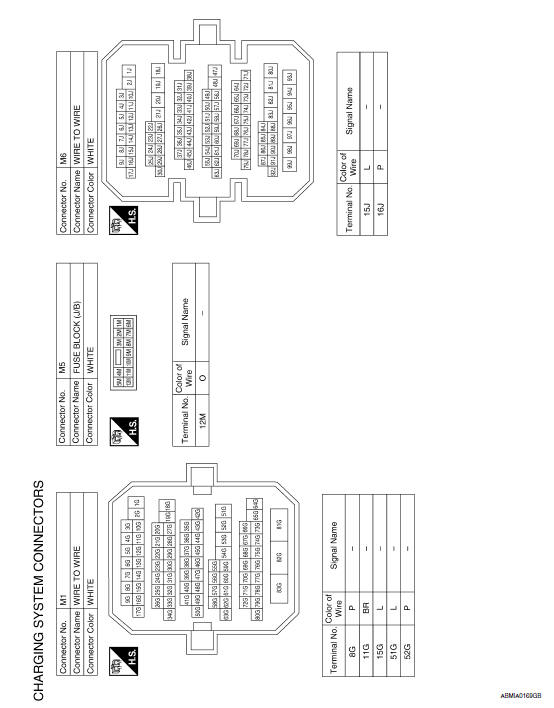
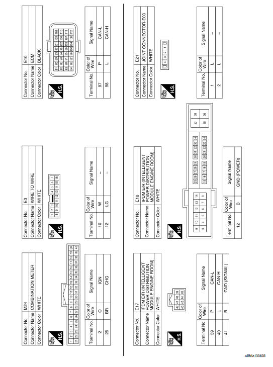
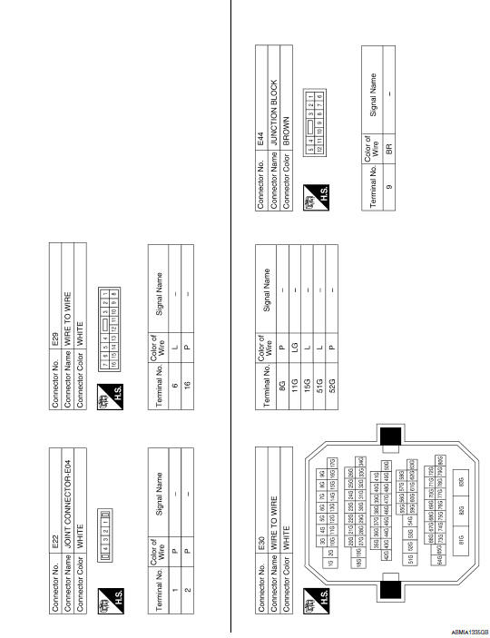
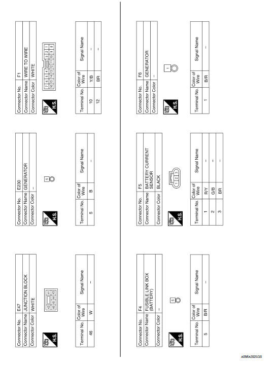
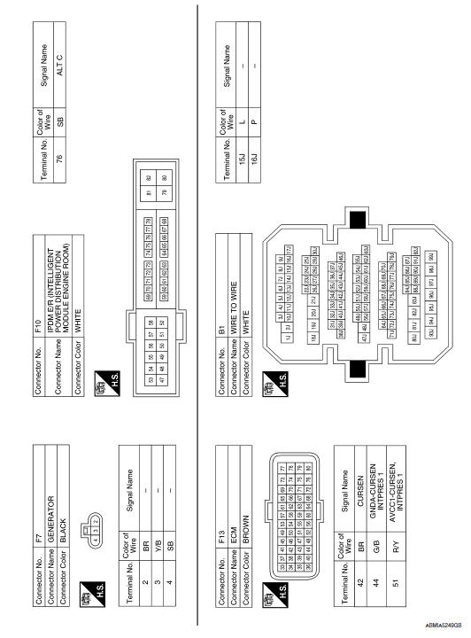
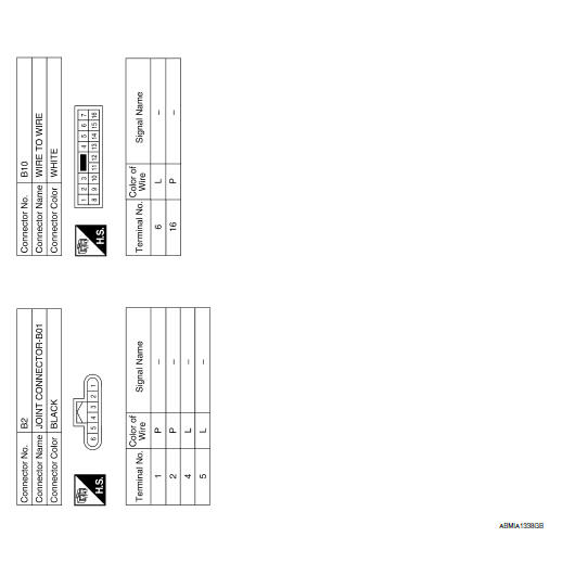
Wiring Diagram
 L terminal circuit (short)
Description
The terminal "L" circuit controls the charge warning lamp. The charge warning
lamp turns ON when the ignition
switch is set to ON or START. When the generator is providing sufficient ...
 Symptom diagnosis
CHARGING SYSTEM
Symptom Table
Symptom
Reference
Battery discharged
Refer to CHG-2, "Work Flow (With EXP-800 NI or GR8-1200
NI)"
or CHG-5, "Work F ...
Other materials:
Headlamp (HI) circuit
Description
The IPDM E/R (intelligent power distribution module engine room) controls the
headlamp high relay based on inputs from the BCM over the CAN communication
lines. When the headlamp high relay is energized, power flows through fuses
48 and 49, located in the IPDM E/R. Power then flow ...
Parking brake switch
Description
The parking brake switch converts the status of the parking brake pedal to an
electric signal and transmits it to
the combination meter. The combination meter, through CAN communication,
transmits the signal to the ABS
actuator and electric unit (control unit).
Component Functi ...
RGB AREA (YS) signal circuit
Description
Transmits the display area of RGB image displayed by AV control unit with RGB
area (YS) signal to display unit.
Diagnosis Procedure
1.CHECK CONTINUITY RGB AREA (YS) SIGNAL CIRCUIT
Turn ignition switch OFF.
Disconnect display unit connector M141 and AV control unit
conne ...
Nissan Maxima Owners Manual
- Illustrated table of contents
- Safety-Seats, seat belts and supplemental restraint system
- Instruments and controls
- Pre-driving checks and adjustments
- Monitor, climate, audio, phone and voice recognition systems
- Starting and driving
- In case of emergency
- Appearance and care
- Do-it-yourself
- Maintenance and schedules
- Technical and consumer information
Nissan Maxima Service and Repair Manual

0.0073