Nissan Maxima Service and Repair Manual: ECU diagnosis information
BCM (BODY CONTROL MODULE)
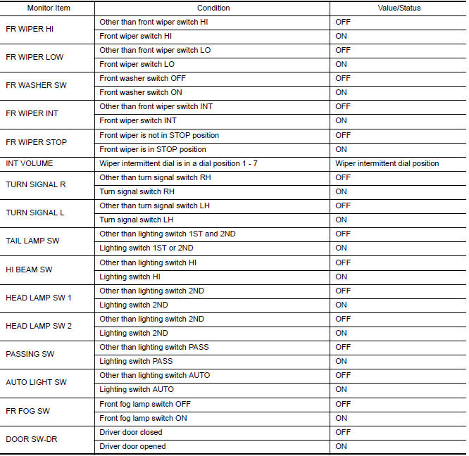
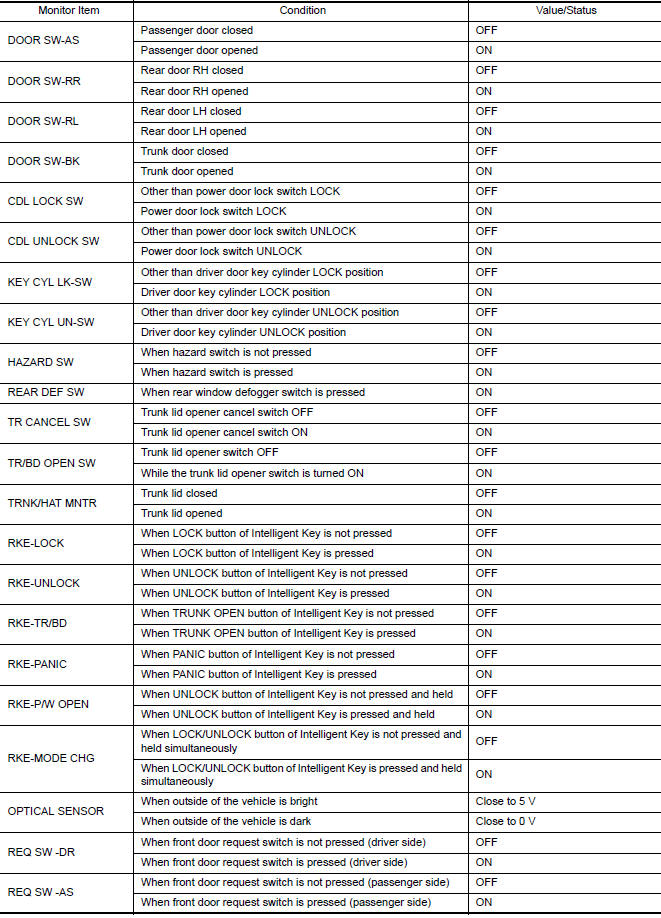
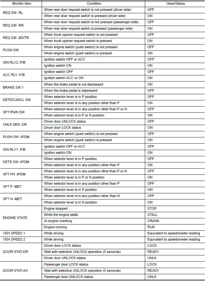
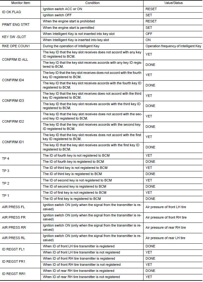
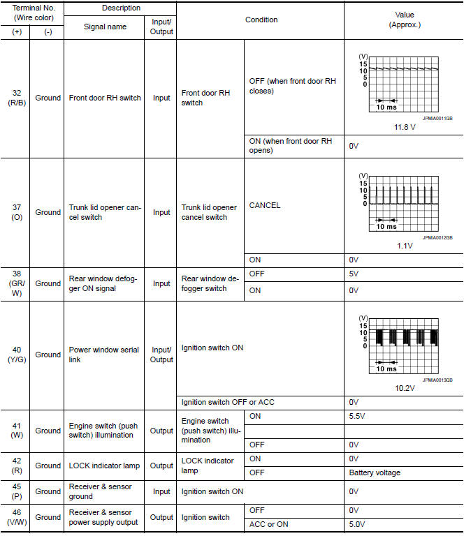
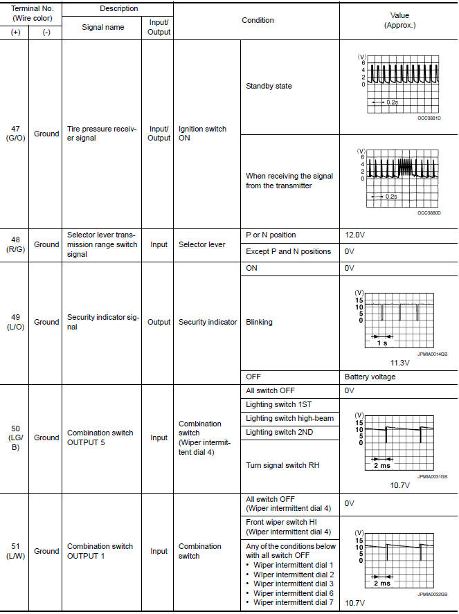
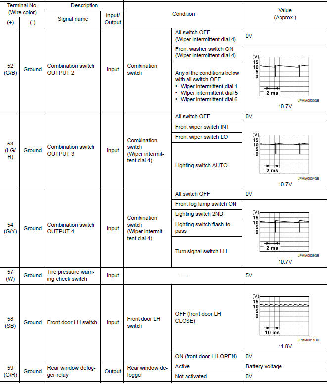
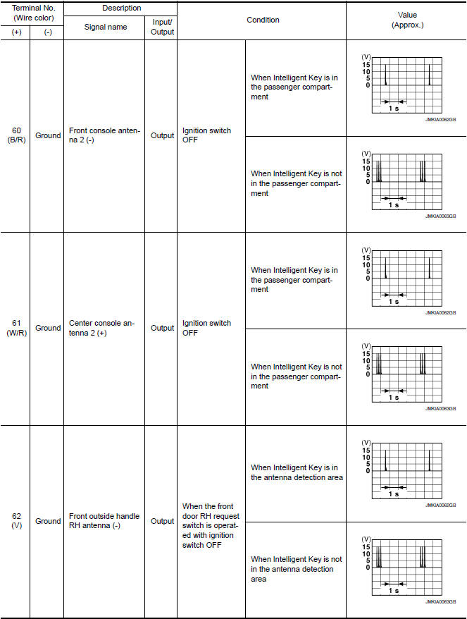
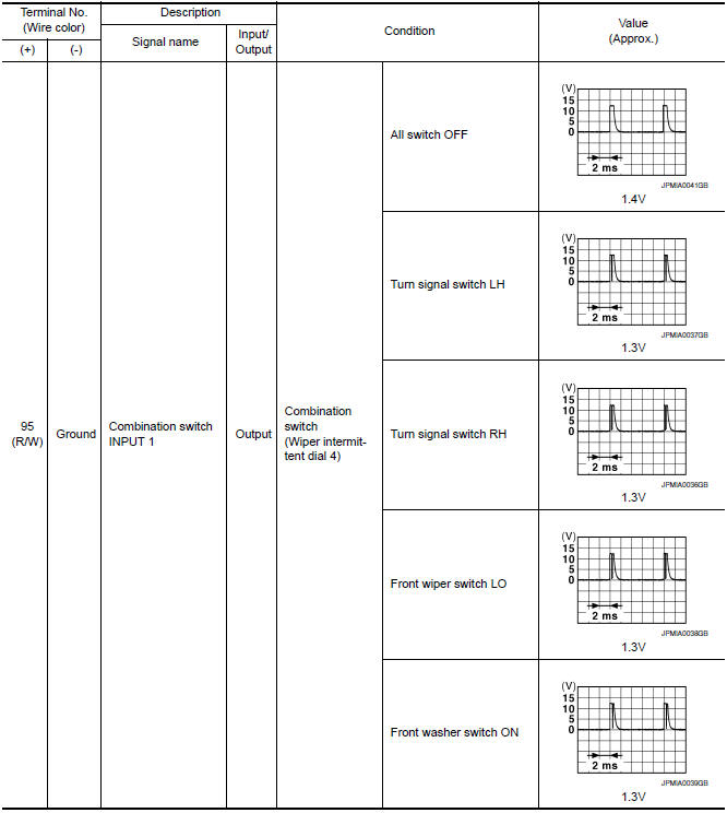
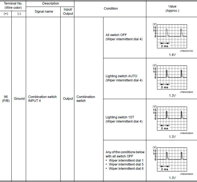
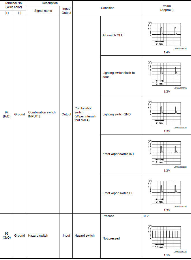
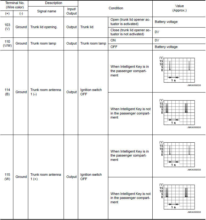
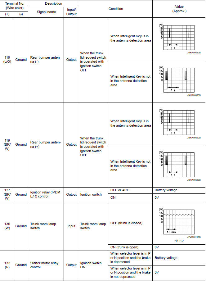
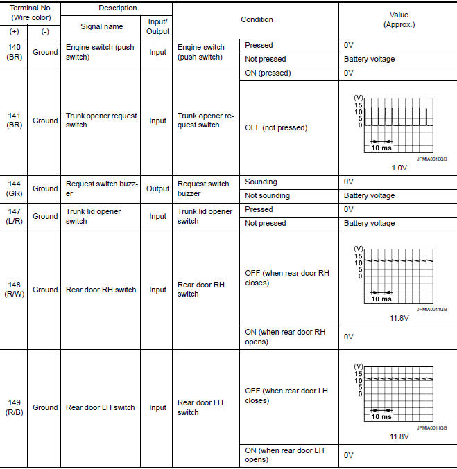
Reference Value
NOTE: The Signal Tech II Tool (J-50190) can be used to perform the following functions. Refer to the Signal Tech II User Guide for additional information.
- Activate and display TPMS transmitter IDs
- Display tire pressure reported by the TPMS transmitter
- Read TPMS DTCs
- Register TPMS transmitter IDs
- Check Intelligent Key relative signal strength
- Confirm vehicle Intelligent Key antenna signal strength
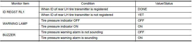
VALUES ON THE DIAGNOSIS TOOL
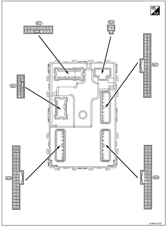
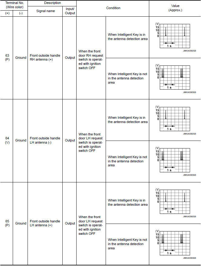
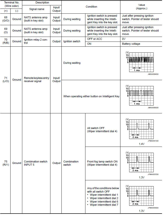
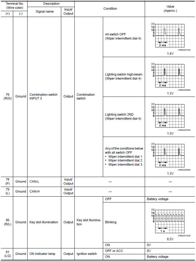
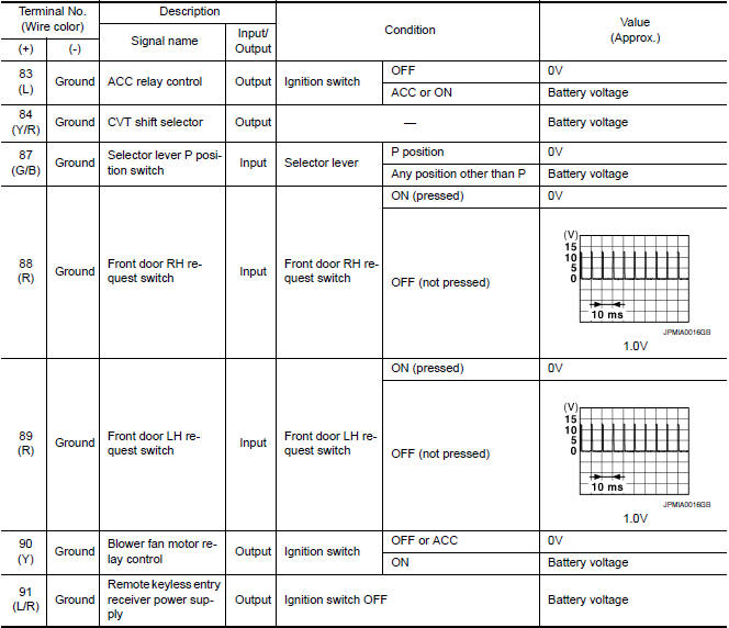
Terminal Layout
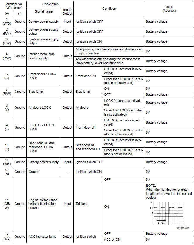
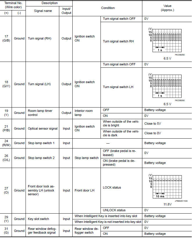
Physical Values
Self-Diagnosis (With CONSULT)
NOTE: The Signal Tech II Tool (J-50190) can be used to perform the following functions. Refer to the Signal Tech II User Guide for additional information.
- Activate and display TPMS transmitter IDs
- Display tire pressure reported by the TPMS transmitter
- Read TPMS DTCs
- Register TPMS transmitter IDs
FUNCTION
Self-Diagnostic Results Mode
NOTE: Before performing the self-diagnosis, be sure to register the ID or else the actual malfunction location may be different from that displayed on CONSULT.
Self-Diagnosis (Without CONSULT)
NOTE: The Signal Tech II Tool (J-50190) can be used to perform the following functions. Refer to the Signal Tech II User Guide for additional information.
- Activate and display TPMS transmitter IDs
- Display tire pressure reported by the TPMS transmitter
- Read TPMS DTCs
- Register TPMS transmitter IDs
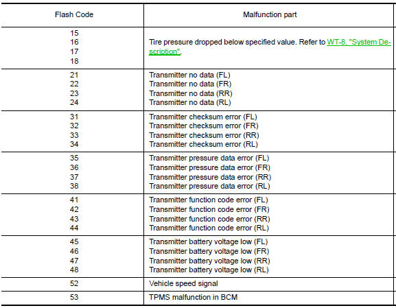
SELF DIAGNOSTIC PROCEDURE (WITHOUT CONSULT)
- Turn ignition switch ON.
- Ground the tire pressure warning check connector to initiate self diagnosis.
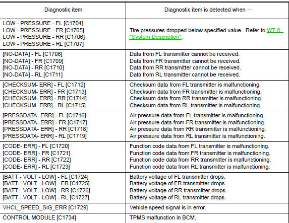
- Compare the flashing pattern with the flash code chart below.
NOTE: The system is normal when the low tire pressure warning lamp flashes 5 times and continues repeating. Selfdiagnosis results are erased automatically by turning the ignition switch OFF.
 C1734 control unit
Description
An internal malfunction has been detected in the TPMS function of the BCM.
DTC Logic
NOTE: The Signal Tech II Tool (J-50190) can
be used to perform the following functions. Refer to t ...
 Wiring diagram
TIRE PRESSURE MONITORING SYSTEM
Wiring Diagram
...
Other materials:
P1611 ID discord, IMMU-ECM
Description
BCM performs the ID verification with ECM that allows the
engine to start. Start the engine if the ID is OK.
ECM prevents the engine from starting if the ID is not registered. BCM starts
the communication with ECM if
ignition switch is turned ON.
DTC Logic
DTC DETECTION LOGIC ...
Daytime running light system
System Diagram
System Description
The headlamp system for Canada vehicles is equipped with a daytime light
relay that activates the high beam headlamps at approximately half
illumination whenever the engine is running. If the parking brake is
depressed before the engine is started, the day ...
Diagnosis and repair workflow
Work Flow
OVERALL SEQUENCE
DETAILED FLOW
1. GET INFORMATION FOR SYMPTOM
Get the detailed information from the customer about the symptom (the
condition and the environment when the incident/malfunction occurred).
2. CHECK DTC
Check DTC.
Perform the following procedure if DTC is displa ...
Nissan Maxima Owners Manual
- Illustrated table of contents
- Safety-Seats, seat belts and supplemental restraint system
- Instruments and controls
- Pre-driving checks and adjustments
- Monitor, climate, audio, phone and voice recognition systems
- Starting and driving
- In case of emergency
- Appearance and care
- Do-it-yourself
- Maintenance and schedules
- Technical and consumer information
Nissan Maxima Service and Repair Manual

0.0053