Nissan Maxima Service and Repair Manual: C1734 control unit
Description
An internal malfunction has been detected in the TPMS function of the BCM.
DTC Logic
NOTE: The Signal Tech II Tool (J-50190) can be used to perform the following functions. Refer to the Signal Tech II User Guide for additional information.
- Activate and display TPMS transmitter IDs
- Display tire pressure reported by the TPMS transmitter
- Read TPMS DTCs
- Register TPMS transmitter IDs
DTC DETECTION LOGIC

DTC CONFIRMATION PROCEDURE
1.CHECK SELF-DIAGNOSTIC RESULTS
- On "SELECT DIAG MODE", select the "SELF-DIAG RESULT" screen.
- Check display contents on "SELF DIAG RESULT" screen.
Diagnosis Procedure
NOTE: The Signal Tech II Tool (J-50190) can be used to perform the following functions. Refer to the Signal Tech II User Guide for additional information.
- Activate and display TPMS transmitter IDs
- Display tire pressure reported by the TPMS transmitter
- Read TPMS DTCs
- Register TPMS transmitter IDs
MALFUNCTION CODE NO. 53 (DTC C1734)
1.SELF-DIAGNOSTIC RESULTS
- On "SELECT DIAG" mode, select the "SELF-DIAG RESULT" screen for BCM.
- Check display contents on "SELF-DIAG RESULT".
2.CHECK BCM HARNESS CONNECTORS
Check BCM harness connectors for damage or loose connections
3.BCM POWER SUPPLY AND GROUND
Check BCM power supply and groun
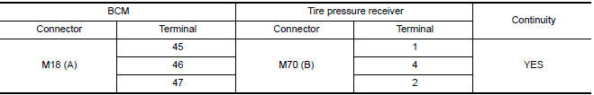
4.CHECK HARNESS BETWEEN BCM AND TIRE PRESSURE RECEIVER
- Turn ignition switch OFF.
- Disconnect BCM harness connector and tire pressure receiver harness connector.
- Check continuity between BCM harness connector M18 (A) and tire pressure receiver harness connector M70 (B).
5.BCM INPUT/OUTPUT SIGNALS
Check BCM input/output signals.
Special Repair Requirement
Perform preliminary ch
 C1729 vehicle speed signal
Description
The vehicle speed signal is not being detected by the BCM.
DTC Logic
NOTE: The Signal Tech II Tool (J-50190) can be used
to perform the following functions. Refer to the Signal Tech I ...
 ECU diagnosis information
BCM (BODY CONTROL MODULE)
Reference Value
NOTE: The Signal Tech II Tool (J-50190) can be used
to perform the following functions. Refer to the Signal Tech II User Guide
for additional informatio ...
Other materials:
Heater and Air Conditioner (automatic)
Front defroster button
Temperature control dial (driver's side)/
AUTO button
Display screen
Temperature control dial (passenger's
side)/DUAL button
Fresh air intake button
Air recirculation button
(air conditioner) button
(manual air flow control)
button
(fan speed cont ...
Rocker Cover
Exploded View
Camshaft position sensors (LH)
O-rings
Camshaft position sensors (RH)
O-rings
Rocker cover (RH)
Rocker cover gasket (RH)
Rocker cover gasket (LH)
Rocker cover (LH)
Refer to INSTALLATION
Front
Removal and Installation (LH)
REMOVAL
Remove the ...
Front combination lamp
Exploded View
Front combination lam
Removal and Installation
FRONT COMBINATION LAMP
Removal
Remove the front bumper fascia. Refer to EXT-16, "Removal and
Installation".
Remove the front combination lamp bolts.
Remove the harness clips from the front combination lamp assembly.
...
Nissan Maxima Owners Manual
- Illustrated table of contents
- Safety-Seats, seat belts and supplemental restraint system
- Instruments and controls
- Pre-driving checks and adjustments
- Monitor, climate, audio, phone and voice recognition systems
- Starting and driving
- In case of emergency
- Appearance and care
- Do-it-yourself
- Maintenance and schedules
- Technical and consumer information
Nissan Maxima Service and Repair Manual

0.0058