
Nissan Maxima Service and Repair Manual: Hazard switch
Component Function Check
1.CHECK HAZARD SWITCH SIGNAL BY CONSULT
CONSULT DATA MONITOR
- Turn ignition switch ON.
- Select "HAZARD SW" of BCM (FLASHER) DATA MONITOR item.
- With operating the hazard switch, check the monitor status.

Diagnosis Procedure
1.CHECK HAZARD SWITCH SIGNAL INPUT
- Turn ignition switch OFF.
- Disconnect hazard switch connector.
- Turn ignition switch ON.
- Check voltage between hazard switch harness connector and ground.
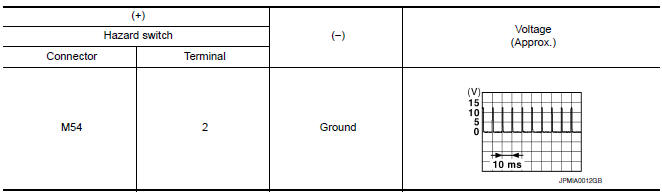
2.CHECK HAZARD SWITCH SIGNAL OPEN CIRCUIT
- Turn ignition switch OFF.
- Disconnect BCM connector M19.
- Check continuity between hazard harness connector and BCM harness connector.

3.CHECK HAZARD SWITCH SIGNAL SHORT CIRCUIT
Check continuity between hazard switch harness connector and ground.

4.CHECK HAZARD SWITCH GROUND OPEN CIRCUIT
Check continuity between hazard switch harness connector and ground.

 Optical sensor
Description
The optical sensor converts the outside brightness (lux) to voltage and
transmits the optical sensor signal to the BCM.
Component Function Check
1.CHECK OPTICAL SENSOR SIG ...

Other materials:
Heater and Air Conditioner (automatic)
Front defroster button
Temperature control dial (driver's side)/
AUTO button
Display screen
Temperature control dial (passenger's
side)/DUAL button
Fresh air intake button
Air recirculation button
(air conditioner) button
(manual air flow control)
button
(fan speed cont ...
System temporarily unavailable
Condition A
When the radar sensor picks up interference
from another radar source, making it impossible
to detect a vehicle ahead, the FEB system is
automatically turned off.
The FEB system warning light (orange) will illuminate.
Action to take
When the above conditions no longer exist, ...
P0841 transmission fluid pressure SEN/SW A
Description
Using the engine load (throttle position), the primary pulley revolution
speed, and the secondary pulley revolution
speed as input signals, TCM changes the operating pressure of the primary pulley
and the secondary pulley
and changes the groove width of the pulley to control the ...
Nissan Maxima Owners Manual
- Illustrated table of contents
- Safety-Seats, seat belts and supplemental restraint system
- Instruments and controls
- Pre-driving checks and adjustments
- Monitor, climate, audio, phone and voice recognition systems
- Starting and driving
- In case of emergency
- Appearance and care
- Do-it-yourself
- Maintenance and schedules
- Technical and consumer information
Nissan Maxima Service and Repair Manual

0.0468