Nissan Maxima Service and Repair Manual: EBD
System Diagram
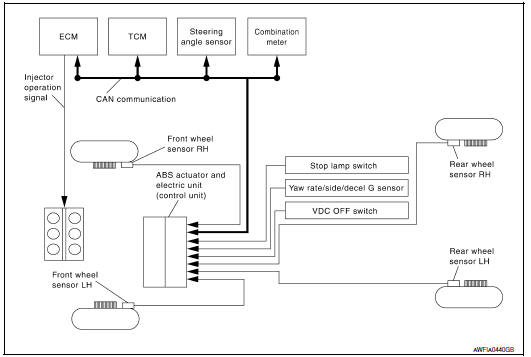
System Description
Electric Brake force Distribution functions as follows:
- ABS actuator and electric unit (control unit) detects subtle slippages between the front and rear wheels during braking. Then it electronically controls the rear braking force (brake fluid pressure) to reduce rear wheel slippage. Accordingly, it improves vehicle stability.
- Electrical system diagnosis by CONSULT is available.
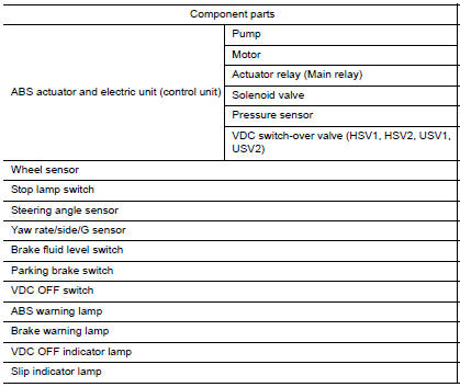
Component Parts Location
- Front wheel sensor LH E19 Front wheel sensor RH E41
- Brake fluid level switch E24
- Parking brake switch E35
- Stop lamp switch E38
- VDC OFF switch M72
- Combination meter M24
- Rear wheel sensor LH C1 Rear wheel sensor RH C2
- Yaw rate/side/decel G sensor M55
- Steering angle sensor M53 (view with steering wheel removed)
- ABS actuator and electric unit (control unit) E26
Component Description
 ABS
ABS
System Diagram
System Description
Anti-Lock Braking System is a function that detects wheel revolution
while braking, electronically controls
braking force, and prevents wheel locking d ...
 Diagnosis system [ABS actuator and electric unit (control unit)]
CONSULT Function (ABS)
FUNCTION
CONSULT can display each diagnostic item using the following diagnostic test
modes.
Diagnostic test mode
Function
ECU Identification
...
Other materials:
Inspection and adjustment
ECM RE-COMMUNICATING FUNCTION
ECM RE-COMMUNICATING FUNCTION : Description
the ECM has been replaced with a new one (*1).
*1: New one means an ECM which has never been energized on-board.
(In this step, initialization procedure by CONSULT is not necessary)
NOTE:
When registering new Key ...
RGB synchronizing signal circuit
Description
Transmit the RGB synchronizing signal to the display unit so as to
synchronize the RGB image displayed with
AV control unit.
Diagnosis Procedure
1.CHECK CONTINUITY RGB SYNCHRONIZING SIGNAL CIRCUIT
Turn ignition switch OFF.
Disconnect display unit connector M141 and AV co ...
P1551, P1552 battery current sensor
Description
The power generation voltage variable control enables fuel consumption to be
decreased by reducing the
engine load which is caused by the power generation of the generator. The
battery current sensor is installed
to the battery cable at the negative terminal. The sensor measures ...
Nissan Maxima Owners Manual
- Illustrated table of contents
- Safety-Seats, seat belts and supplemental restraint system
- Instruments and controls
- Pre-driving checks and adjustments
- Monitor, climate, audio, phone and voice recognition systems
- Starting and driving
- In case of emergency
- Appearance and care
- Do-it-yourself
- Maintenance and schedules
- Technical and consumer information
Nissan Maxima Service and Repair Manual

0.0117