Nissan Maxima Service and Repair Manual: Diagnosis system [ABS actuator and electric unit (control unit)]
CONSULT Function (ABS)
FUNCTION
CONSULT can display each diagnostic item using the following diagnostic test modes.
|
Diagnostic test mode |
Function |
| ECU Identification | ABS actuator and electric unit (control unit) part number can be read |
| Self Diagnostic Result | Displays ABS actuator and electric unit (control unit) self-diagnosis results |
| Data Monitor | Displays ABS actuator and electric unit (control unit) input/output data in real time. |
| Active Test | Operation of electrical loads can be checked by sending drive signals to them |
| Work support | Supports inspections and adjustments. Commands are transmitted to the ABS actuator and electric unit (control unit) for setting the status suitable for required operation, input/output signals are received from the ABS actuator and electric unit (control unit) and received data is displayed. |
| CAN Diag Support Monitor | The result of transmit/receive diagnosis of CAN communication can be read. |
SELF DIAGNOSTIC RESULT MODE
Operation Procedure
Before performing the self-diagnosis, start engine and drive vehicle at 30 km/h (19 MPH) or more for approximately 1 minute.
How to Erase Self-Diagnosis Results
After erasing DTC memory, start engine and drive vehicle at 30 km/h (19 MPH) or more for approximately 1 minute as the final inspection, and make sure that the ABS warning lamp, VDC OFF indicator lamp, SLIP indicator lamp and brake warning lamp turn OFF.
CAUTION: If memory cannot be erased, perform applicable diagnosis.
NOTE:
- When the wheel sensor malfunctions, after inspecting the wheel sensor system, the ABS warning lamp, SLIP indicator lamp and brake warning lamp will not turn OFF even when the system is normal unless the vehicle is driving at approximately 30 km/h (19 MPH) or more for approximately 1 minute.
- Brake warning lamp will turn ON in case of parking brake operation (when switch is ON) or of brake fluid level switch operation (when brake fluid is insufficient).
- VDC OFF switch should not stay in "ON" position.
Display Item List
DATA MONITOR
Display Item List
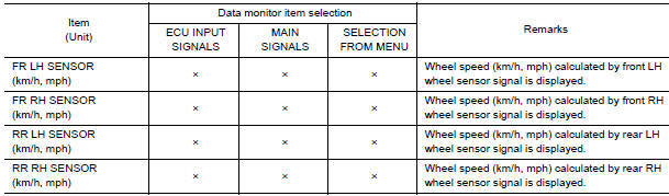
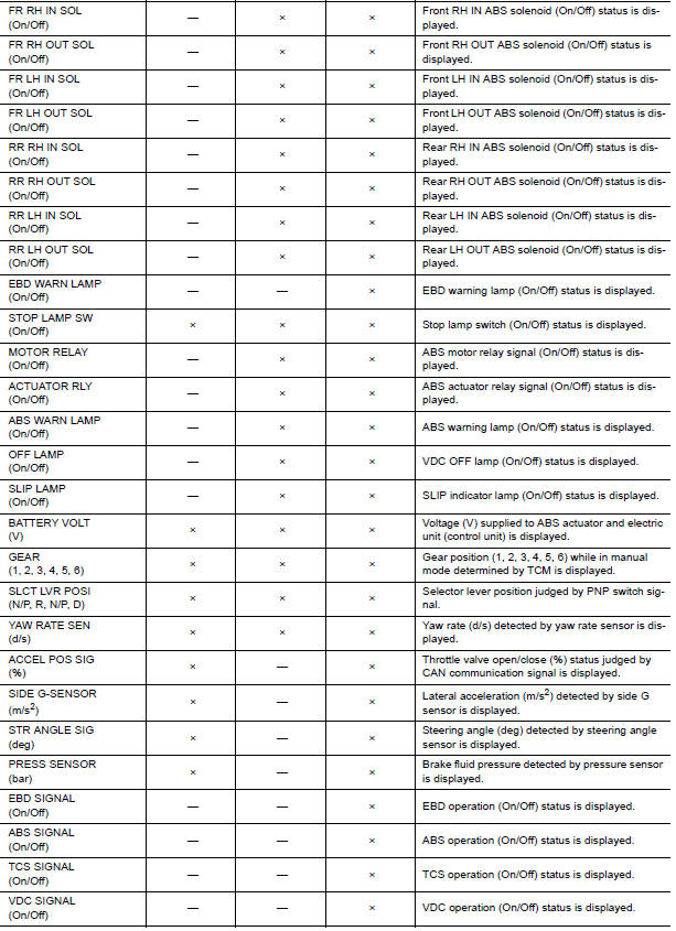
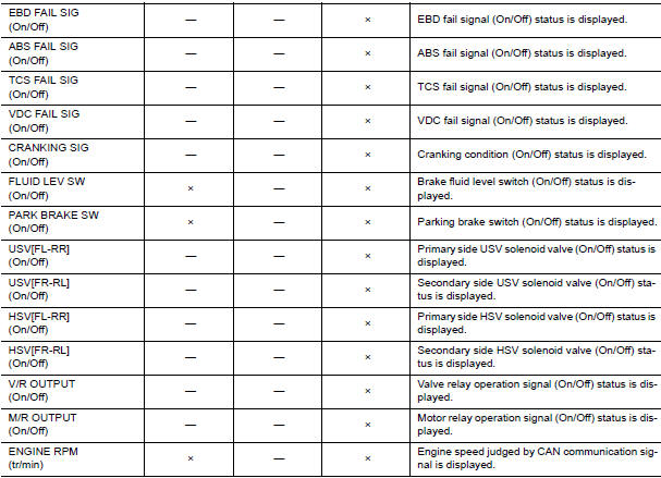
×: Applicable
-: Not applicable
ACTIVE TEST
CAUTION:
- Do not perform active test while driving vehicle.
- Make sure to completely bleed air from brake system.
- The active test cannot be performed with the ABS warning lamp, VDC indicator lamp, SLIP indicator lamp or brake warning lamp on.
- ABS warning lamp, VDC OFF indicator lamp, SLIP indicator lamp and brake warning lamp are on during active test.
NOTE:
- When active test is performed while depressing the pedal, the pedal depression amount will change. This is normal. (Only solenoid valve and ABS motor)
- "TEST IS STOPPED" is displayed 10 seconds after operation start.
- After "TEST IS STOPPED" is displayed, to perform test again, touch BACK.
Test Item
SOLENOID VALVE
- When performing an active test of the ABS function, select "MAIN SIGNALS" for each test item.
- For ABS solenoid valve, touch "Up", "Keep", and "Down" on the display screen. For ABS solenoid valve (ACT), touch "Up", "ACT UP", "ACT KEEP" and confirm that solenoid valves operate as shown in the table below.
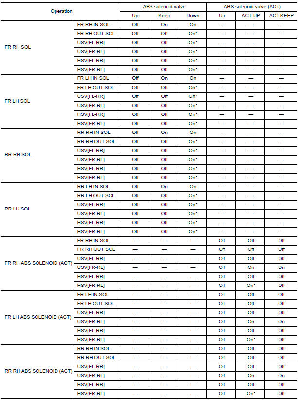
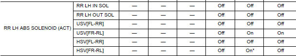
*: On for 1 to 2 seconds after the touch, and then Off
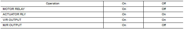
ABS MOTOR
- Touch "On" and "Off" on screen. Make sure motor relay, actuator relay, V/R output and M/R output operate as shown in table below.
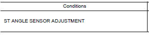
WORK SUPPORT
 EBD
EBD
System Diagram
System Description
Electric Brake force Distribution functions as follows:
ABS actuator and electric unit (control unit) detects subtle
slippages between the front and rear ...

Other materials:
B2581, B2582 intake sensor
Description
Intake Sensor
The intake sensor is located on the evaporator.
It converts air temperature after it passes through the evaporator
into a resistance value which is then input to the A/C auto amp.
Intake Sensor Circuit
DTC Logic
DTC DETECTION LOGIC
NOTE:
If DTC is di ...
P1574 ASCD vehicle speed sensor
Description
The ECM receives two vehicle speed signals via the CAN communication line.
One is sent from combination
meter, and the other is from TCM (Transmission control module). The ECM uses
these signals for ASCD control.
Refer to EC-68, "System Diagram" for ASCD functions.
D ...
Basic inspection
DIAGNOSIS AND REPAIR WORKFLOW
Work Flow
OVERALL SEQUENCE
DETAILED FLOW
1. GET INFORMATION FOR SYMPTOM
Get the detailed information from the customer about the symptom (the
condition and the environment when
the incident/malfunction occurred).
2. CHECK DTC
Check DTC.
Perform the f ...
Nissan Maxima Owners Manual
- Illustrated table of contents
- Safety-Seats, seat belts and supplemental restraint system
- Instruments and controls
- Pre-driving checks and adjustments
- Monitor, climate, audio, phone and voice recognition systems
- Starting and driving
- In case of emergency
- Appearance and care
- Do-it-yourself
- Maintenance and schedules
- Technical and consumer information
Nissan Maxima Service and Repair Manual

0.0053