Nissan Maxima Service and Repair Manual: RGB (G: green) signal circuit
Description
Transmit the image displayed with AV control unit with RGB signal to the display unit.
Diagnosis Procedure
1.CHECK CONTINUITY RGB (G: GREEN) SIGNAL CIRCUIT
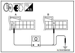
- Turn ignition switch OFF.
- Disconnect display unit connector M141 and AV control unit connector M117.
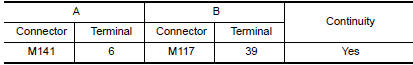
- Check continuity between display unit harness connector M141 (A) terminal 6 and AV control unit harness connector M117 (B) terminal 39.
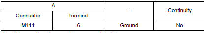
- Check continuity between display unit harness connector M141 (A) terminal 6 and ground.
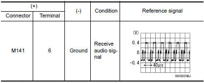
2.CHECK RGB (G: GREEN) SIGNAL
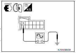
- Connect display unit connector M141 and AV control unit connector M117.
- Turn ignition switch ON.
- Check signal between display unit harness connector M141 terminal 6 and ground.
 RGB (R: red) signal circuit
Description
Transmit the image displayed with AV control unit with RGB signal to the
display unit.
Diagnosis Procedure
1.CHECK CONTINUITY RGB (R: RED) SIGNAL CIRCUIT
Turn ignition switch ...
 RGB (B: blue) signal circuit
Description
Transmit the image displayed with AV control unit with RGB signal to the
display unit.
Diagnosis Procedure
1.CHECK CONTINUITY RGB (B: BLUE) SIGNAL CIRCUIT
Turn ignition switch ...
Other materials:
Power outlet
Console Box
The power outlet is for powering electrical accessories
such as cellular telephones. It is rated at
12 volt, 120W (10A) maximum.
The power outlet is powered only when the ignition
switch is in the ACC or ON position.
CAUTION
The outlet and plug may be hot during
or immedi ...
Automatic air conditioner system
System Diagram
CONTROL SYSTEM
The control system consists of input sensors, switches, the A/C auto amp.
(microcomputer) and outputs. The
relationship of these components is as shown in the figure below:
System Description
CONTROL OPERATION
Display
The operation status of the HVAC system ...
Precaution
Precaution for Supplemental Restraint System (SRS) "AIR BAG" and
"SEAT BELT PRE-TENSIONER"
The Supplemental Restraint System such as "AIR BAG" and "SEAT BELT
PRE-TENSIONER", used along with a front seat belt, helps to reduce the risk
or severity of injury to the driver and front passenger for ...
Nissan Maxima Owners Manual
- Illustrated table of contents
- Safety-Seats, seat belts and supplemental restraint system
- Instruments and controls
- Pre-driving checks and adjustments
- Monitor, climate, audio, phone and voice recognition systems
- Starting and driving
- In case of emergency
- Appearance and care
- Do-it-yourself
- Maintenance and schedules
- Technical and consumer information
Nissan Maxima Service and Repair Manual

0.0055