Nissan Maxima Service and Repair Manual: P1801 vias control solenoid valve 2
Description
The VIAS control solenoid valve 2 cuts the intake manifold vacuum signal for power valve 2 control. It responds to ON/OFF signals from the ECM. When the solenoid is OFF, the vacuum signal from the intake manifold is cut. When the ECM sends an ON signal the coil pulls the plunger downward and sends the vacuum signal to the power valve actuator 2.
DTC Logic
DTC DETECTION LOGIC
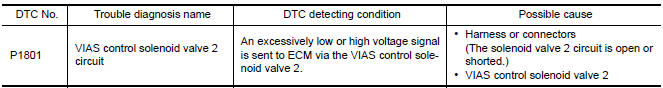
DTC CONFIRMATION PROCEDURE
1.CONDITIONING
If DTC Confirmation Procedure has been previously conducted, always perform the following before conducting the next test.
- Turn ignition switch OFF and wait at least 10 seconds.
- Turn ignition switch ON.
- Turn ignition switch OFF and wait at least 10 seconds.
TESTING CONDITION: Before performing the following procedure, confirm battery voltage is more than 11 V at idle.
2.PERFORM DTC CONFIRMATION PROCEDURE
- Start engine and let it idle for at least 5 seconds.
- Check 1st trip DTC.
Diagnosis Procedure
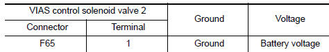
1.CHECK VIAS CONTROL SOLENOID VALVE 2 POWER SUPPLY CIRCUIT
- Turn ignition switch OFF.
- Disconnect VIAS control solenoid valve 2 harness connector.
- Turn ignition switch ON.
- Check the voltage between VIAS control solenoid valve 2 harness connector and ground.
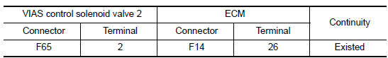
2.CHECK VIAS CONTROL SOLENOID VALVE 2 OUTPUT SIGNAL CIRCUIT FOR OPEN AND SHORT
- Turn ignition switch OFF.
- Disconnect ECM harness connector.
- Check the continuity between VIAS control solenoid valve 2 harness connector and ECM harness connector.
- Also check harness for short to ground and short to power
3.CHECK VIAS CONTROL SOLENOID VALVE 2
4.CHECK INTERMITTENT INCIDENT
Component Inspection
1.CHECK VIAS CONTROL SOLENOID VALVE 2
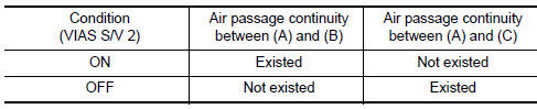
With CONSULT
- Turn ignition switch OFF.
- Reconnect all harness connectors disconnected.
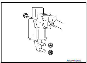
- Disconnect vacuum hoses connected to VIAS control solenoid valve 2.
- Turn ignition switch ON.
- Select "VIAS S/V-2" in "ACTIVE TEST" mode with CONSULT.
- Check air passage continuity and operation delay time under the following conditions.
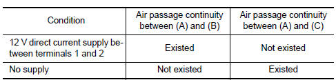
Without CONSULT
- Turn ignition switch OFF.
- Disconnect VIAS control solenoid valve 2 harness connector.
- Disconnect vacuum hoses connected to VIAS volume control solenoid valve 2.
- Check air passage continuity and operation delay time under the following conditions.
 P1800 vias control solenoid valve 1
Description
The VIAS control solenoid valve 1 cuts the intake manifold vacuum signal for
power valve 1 control. It
responds to ON/OFF signals from the ECM. When the solenoid is OFF, the vacuum
...
 P1805 brake switch
Description
Brake switch signal is applied to the ECM via the stop lamp switch when the
brake pedal is depressed. This
signal is used mainly to decrease the engine speed when the vehicle is being ...
Other materials:
Audio system
System Diagram
System Description
AUDIO SYSTEM
The audio system consists of the following components
AV control unit
Display unit
BOSE speaker amp.
Window antenna
Steering wheel audio control switches
A/C and AV switch assembly
Front door speakers
Tweeters
Center speaker
R ...
Rear door speaker
Removal and Installation
REMOVAL
Remove the rear door finisher. Refer to INT-21, "Removal and
Installation".
Remove the rear door speaker screws (A).
Disconnect the harness connector (B) from the rear door speaker
(1) and remove.
INSTALLATION
Installation is in the reverse order ...
Removal and installation
BATTERY
Exploded View
Upper ECM bracket
Battery frame
Battery rods
Battery
Battery tray liner
Battery tray
Removal and Installation (Battery)
REMOVAL
Loosen battery cable assembly nuts, and disconnect both battery
terminals.
CAUTION:
When disconnecting, discon ...
Nissan Maxima Owners Manual
- Illustrated table of contents
- Safety-Seats, seat belts and supplemental restraint system
- Instruments and controls
- Pre-driving checks and adjustments
- Monitor, climate, audio, phone and voice recognition systems
- Starting and driving
- In case of emergency
- Appearance and care
- Do-it-yourself
- Maintenance and schedules
- Technical and consumer information
Nissan Maxima Service and Repair Manual

0.0055