Nissan Maxima Service and Repair Manual: P1805 brake switch
Description
Brake switch signal is applied to the ECM via the stop lamp switch when the brake pedal is depressed. This signal is used mainly to decrease the engine speed when the vehicle is being driver.
DTC Logic
DTC DETECTION LOGIC
DTC CONFIRMATION PROCEDURE
1.PERFORM DTC CONFIRMATION PROCEDURE
- Turn ignition switch ON.
- Fully depress the brake pedal for at least 5 seconds.
- Erase the DTC.
- Check 1st trip DTC.
Diagnosis Procedure
1.CHECK STOP LAMP SWITCH CIRCUIT
- Turn ignition switch OFF.
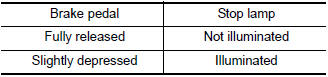
- Check the stop lamp when depressing and releasing the brake pedal.
2.CHECK STOP LAMP SWITCH POWER SUPPLY CIRCUIT
- Disconnect stop lamp switch harness connector.
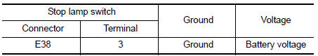
- Check the voltage between stop lamp switch harness connector and ground.
3.DETECT MALFUNCTIONING PART
Check the following.
- Fuse block (J/B) connector E6
- 10 A fuse (No. 7)
- Harness for open or short between battery and stop lamp switch
4.CHECK STOP LAMP SWITCH INPUT SIGNAL CIRCUIT FOR OPEN AND SHORT
- Disconnect stop lamp switch harness connector.
- Disconnect ECM harness connector.
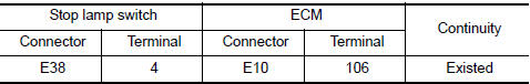
- Check the continuity between stop lamp switch harness connector and ECM harness connector.
- Also check harness for short to ground and short to power.
5.DETECT MALFUNCTIONING PART
Check the following.
- Fuse block (J/B) connector E6
- Junction block connectors E44, E45
- Harness for open or short between ECM and stop lamp switch
6.CHECK STOP LAMP SWITC
7.CHECK INTERMITTENT INCIDENT
Component Inspection (Stop Lamp Switch)
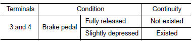
1.CHECK STOP LAMP SWITCH-I
- Turn ignition switch OFF.
- Disconnect stop lamp switch harness connector.
- Check harness continuity between stop lamp switch terminals under the following conditions.
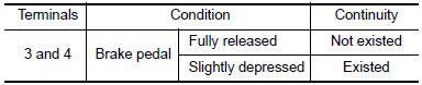
2.CHECK STOP LAMP SWITCH-II
- Adjust stop lamp switch installation. Refer to BR-18, "Removal and Installation".
- Check harness continuity between stop lamp switch terminals under the following conditions.
 P1801 vias control solenoid valve 2
Description
The VIAS control solenoid valve 2 cuts the intake manifold vacuum signal for
power valve 2 control. It
responds to ON/OFF signals from the ECM. When the solenoid is OFF, the vacuum
...
 P2096, P2097, P2098, P2099 A/F sensor 1
Description
The air fuel ratio (A/F) sensor 1 is a planar one-cell limit current sensor.
The sensor element of the A/F sensor 1 is composed an electrode
layer, which transports ions. It has a he ...
Other materials:
Bluetooth control unit
Removal and Installation
REMOVAL
Disconnect the battery negative terminal. Refer to PG-67, "Removal
and Installation (Battery)".
Remove the trunk upper finisher. Refer to INT-23, "Exploded View".
Remove the parcel shelf finisher. Refer to INT-28, "Removal and
Installation".
From i ...
Main line between HVAC and A-bag circuit
Diagnosis Procedure
1.CHECK HARNESS CONTINUITY (OPEN CIRCUIT)
Turn the ignition switch OFF.
Disconnect the battery cable from the negative
terminal.
Disconnect the following harness connectors.
A/C auto amp.
Harness connectors M1 and ...
Power supply and ground circuit
Description
EPS system functions by ignition power supply.
Diagnosis Procedure
1.CHECK POWER SUPPLY
Turn the ignition switch OFF.
Disconnect power steering control unit connector.
Turn the ignition switch ON.
Check voltage between power steering control unit connectorM59
terminal 3 ...
Nissan Maxima Owners Manual
- Illustrated table of contents
- Safety-Seats, seat belts and supplemental restraint system
- Instruments and controls
- Pre-driving checks and adjustments
- Monitor, climate, audio, phone and voice recognition systems
- Starting and driving
- In case of emergency
- Appearance and care
- Do-it-yourself
- Maintenance and schedules
- Technical and consumer information
Nissan Maxima Service and Repair Manual

0.006