Nissan Maxima Service and Repair Manual: P2096, P2097, P2098, P2099 A/F sensor 1
Description
The air fuel ratio (A/F) sensor 1 is a planar one-cell limit current sensor.
The sensor element of the A/F sensor 1 is composed an electrode layer, which transports ions. It has a heater in the element.
The sensor is capable of precise measurement = 1, but also in the lean and rich range. Together with its control electronics, the sensor outputs a clear, continuous signal throughout a wide range.
The exhaust gas components diffuse via the diffusion layer at the sensor cell. An electrode layer is applied voltage, and this current relative oxygen density in lean. Also this current relative hydrocarbon density in rich.
Therefore, the A/F sensor 1 is able to indicate air fuel ratio by this electrode layer of current. In addition, a heater is integrated in the sensor to ensure the required operating temperature of about 800C (1,472F).
DTC Logic
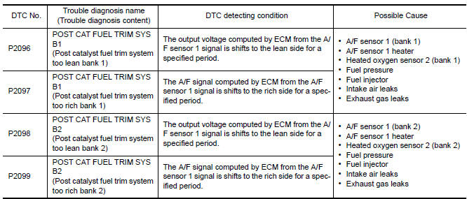
DTC DETECTION LOGIC
DTC CONFIRMATION PROCEDURE
1.PRECONDITIONING
If DTC Confirmation Procedure has been previously conducted, always perform the following before conducting the next test.
- Turn ignition switch OFF andwait at least 10 seconds.
- Turn ignition switch ON.
- Turn ignition switch OFF and wait at least 10 seconds.
TESTING CONDITION: Before performing the following procedure, confirm that battery voltage is more than 11 V at idle.
2.PERFORM DTC CONFIRMATION PROCEDURE
- Clear the mixture ratio self-learning value. Refer to EC-24, "MIXTURE RATIO SELF-LEARNING VALUE CLEAR : Special Repair Requirement".
- Turn ignition switch OFF and wait at least 10 seconds.
- Turn ignition switch ON.
- Turn ignition switch OFF and wait at least 10 seconds.
- Start engine and keep the engine speed between 3,500 and 4,000 rpm for 1 minute under no load.
- Let engine idle for 1 minute.
- Keep engine speed between 2,500 and 3,000 rpm for 20 minutes.
- Check 1st trip DTC.
Diagnosis Procedure
1.CHECK GROUND CONNECTION
- Turn ignition switch OFF.
- Check ground connection E9.
2.RETIGHTEN A/F SENSOR 1 AND HEATED OXYGEN SENSOR 2
Loosen and retighten the A/F sensor 1 and heated oxygen sensor 2.
3.CHECK FOR EXHAUST GAS LEAK
- Start engine and run it at idle.
- Listen for an exhaust gas leak before the three way catalyst 2.
4.CHECK FOR INTAKE AIR LEAKAGE
- Start engine and run it at idle.
- Listen for an intake air leakage after the mass air flow sensor.
5.CLEAR THE MIXTURE RATIO SELF-LEARNING VALUE
- Clear the mixture ratio self-learning value. Refer to EC-24, "MIXTURE RATIO SELF-LEARNING VALUE CLEAR : Special Repair Requirement".
- Run engine for at least 10 minutes at idle speed.
6.CHECK HARNESS CONNECTOR
- Turn ignition switch OFF.
- Disconnect A/F sensor 1 harness connector.
- Check that water is not inside connectors.
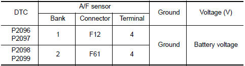
7.CHECK AIR FUEL RATIO (A/F) SENSOR 1 POWER SUPPLY CIRCUIT
- Disconnect A/F sensor 1 harness connector.
- Turn ignition switch ON.
- Check the voltage between A/F sensor 1 harness connector and ground.
8.DETECT MALFUNCTIONING PART
Check the following.
- IPDM E/R harness connector F10
- 15 A fuse (No. 37)
- Harness for open or short between A/F sensor 1 and fuse
9.CHECK A/F SENSOR 1 INPUT SIGNAL CIRCUIT FOR OPEN AND SHORT
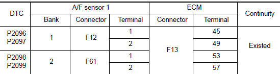
- Turn ignition switch OFF.
- Disconnect ECM harness connector.
- Check the continuity between A/F sensor 1 harness connector and ECM harness connector
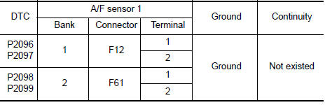
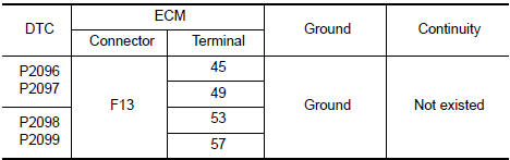
- Check the continuity between A/F sensor 1 harness connector and ground, or ECM harness connector and ground.
- Also check harness for short to power.
10.CHECK A/F SENSOR 1 HEA
11.CHECK HEATED OXYGEN SENSOR 2
12.CHECK INTERMITTENT INCIDENT
13.REPLACE AIR FUEL RATIO (A/F) SENSOR 1
Replace malfunctioning air fuel ratio (A/F) sensor 1.
CAUTION:
- Discard any A/F sensor which has been dropped from a height of more than 0.5 m (19.7 in) onto a hard surface such as a concrete floor; use a new one.
- Before installing new A/F sensor, clean exhaust system threads using Oxygen Sensor Thread Cleaner [commercial service tool (J-43897-18 or J-43897-12)] and approved anti-seize lubricant (commercial service tool).
14.CONFIRM A/F ADJUSTMENT DATA
With CONSULT
- Turn ignition switch ON.
- Select "A/F ADJ-B1" and "A/F ADJ-B2" in "DATA MONITOR" mode with CONSULT.
- Make sure that "0.000" is displayed on CONSULT screen.
15.CLEAR THE MIXTURE RATIO SELF-LEARNING VALUE
Clear the mixture ratio self-learning value.
16.CONFIRM A/F ADJUSTMENT DATA
With CONSULT
- Turn ignition switch ON.
- Select "A/F ADJ-B1" and "A/F ADJ-B2" in "DATA MONITOR" mode with CONSULT.
- Make sure that "0.000" is displayed on CONSULT screen.
 P1805 brake switch
Description
Brake switch signal is applied to the ECM via the stop lamp switch when the
brake pedal is depressed. This
signal is used mainly to decrease the engine speed when the vehicle is being ...
 P2100, P2103 throttle control motor relay
Description
Power supply for the throttle control motor is provided to the ECM via the
throttle control motor relay. The throttle
control motor relay is controlled ON/OFF by the ECM. When the ign ...
Other materials:
Spark plugs
Replacing spark plugs
Iridium-tipped spark plugs
It is not necessary to replace iridium-tipped A
spark plugs as frequently as conventional type
spark plugs because they last much longer. Follow
the maintenance log shown in the "Maintenance
and schedules" section of this manual. Do
not ser ...
Diagnosis system (bluetooth control unit)
Diagnosis Description
The Bluetooth control unit has two diagnostic checks. The first diagnostic
check is performed automatically every ignition cycle during control unit
initialization. The second diagnostic check is performed by the technician
using the steering wheel audio control switches ...
Engine compartment check locations
VQ35DE engine
Engine coolant reservoir
Drive belt location
Engine oil filler cap
Brake fluid reservoir
Air cleaner
Fuse block
Fuse block/Fusible links
Fusible links
Battery
Engine oil dipstick
Radiator cap
Power steering fluid reservoir
Windshield-washer fluid reservo ...
Nissan Maxima Owners Manual
- Illustrated table of contents
- Safety-Seats, seat belts and supplemental restraint system
- Instruments and controls
- Pre-driving checks and adjustments
- Monitor, climate, audio, phone and voice recognition systems
- Starting and driving
- In case of emergency
- Appearance and care
- Do-it-yourself
- Maintenance and schedules
- Technical and consumer information
Nissan Maxima Service and Repair Manual

0.0063