Nissan Maxima Service and Repair Manual: Variable induction air system
System Diagram
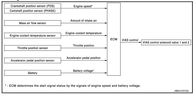
System Description
INPUT/OUTPUT SIGNAL CHART
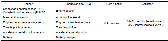
*: ECM determines the start signal status by the signals of engine speed and battery voltage.
SYSTEM DESCRIPTION
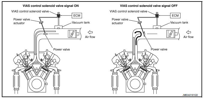
In the medium speed range, the power valves are closed. Under this condition, the pressure waves of the exhaust stroke do not disturb the pressure waves of the intake stroke of each opposite bank. Therefore, charging efficiency is increased together with the effect of the long intake passage.
However, in the high speed range, the power valves are open. Under this condition, the pressure waves of intake stroke are resonant with those of each opposite bank exhaust stroke. Therefore, charging efficiency is also increased.
In addition, both valves 1 and 2 are opened or closed in other ranges mentioned above. Thus maximum charging efficiency is obtained for the various driving conditions.
VACUUM HOSE DRAWING
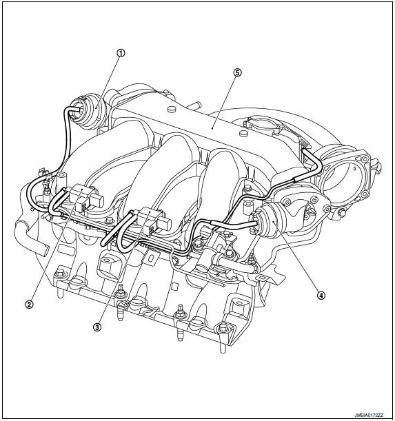
- Power valve actuator 1
- VIAS control solenoid valve 1
- VIAS control solenoid valve 2
- Power valve actuator 2
- Intake manifold collector
Component Parts Location
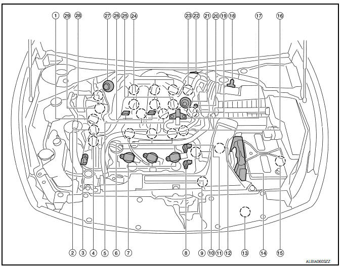
- Intake valve timing control solenoid valve (bank 1)
- Electronic controlled engine mount control solenoid valve
- Exhaust valve timing control magnet retarder (bank 2)
- Intake valve timing control solenoid valve (bank 2)
- Knock sensor (bank 1 and 2)
- Fuel injector (bank 2)
- Ignition coil (with power transistor) and spark plug (bank 2)
- Exhaust valve timing control position sensor (bank 2)
- Crankshaft position sensor (POS)
- Engine coolant temperature sensor
- Camshaft position sensor (PHASE) (bank 2)
- Transmission range switch
- Refrigerant pressure sensor
- ECM
- Battery current sensor
- Condenser-2
- EVAP canister purge volume control solenoid valve
- Mass air flow sensor (with intake air temperature sensor)
- Camshaft position sensor (PHASE) (bank 1)
- EVAP service port
- Power valve actuator 2
- Electric throttle control actuator
- Exhaust valve timing control position sensor (bank 1)
- Ignition coil (with power transistor) and spark plug (bank 1)
- Fuel injector (bank 1)
- VIAS control solenoid valve 1 and 2
- Power valve actuator 1
- Exhaust valve timing control magnet retarder (bank 1)
- Power steering pressure sensor
- Mas air flow sensor (with intake air temperature sensor)
- Air cleaner case
- Engine coolant temperature sensor (view with engine cover removed)
- EVAP canister purge volume control solenoid valve (view with engine cover removed)
- Power valve actuator 1 (view with engine cover removed)
- VIAS control solenoid valve 1
- VIAS control solenoid valve 2
- Power valve actuator 2
- Power steering pressure sensor
- Tie rod (RH)
- Camshaft position sensor (PHASE) (bank 1) (view with air cleaner case removed)
- Exhaust valve timing control position sensor (bank 1)
- Camshaft position sensor (PHASE) (bank 2) (view with air cleaner case removed)
- Exhaust valve timing control position sensor (bank 2)
- Engine oil temperature sensor
 : Vehicle front
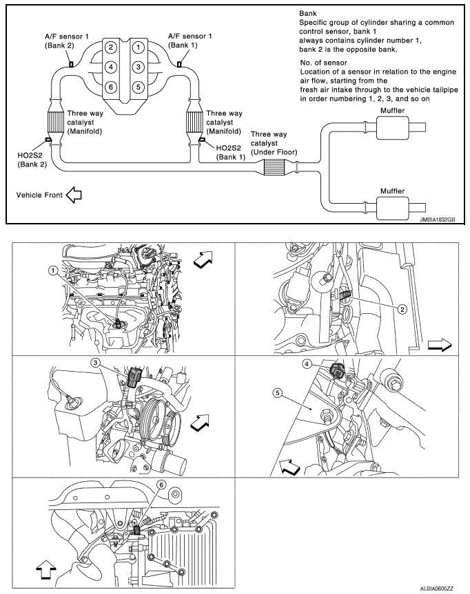
- A/F sensor 1 (bank 1) (view with engine removed)
- A/F sensor 1 (bank 2)
- HO2S2 (bank 1) harness connector (view with engine removed)
- HO2S2 (bank 2) harness connector
- Front engine mount
- Crankshaft position sensor (POS)
 : Vehicle front
- Electronic controlled engine mount control solenoid valve (view with engine cover removed)
- EVAP control system pressure sensor (view with rear suspension member removed)
- EVAP canister vent control valve
- EVAP canister
- Fuel injector harness connector (view with intake manifold collector removed)
- Exhaust valve timing control magnet retarder (bank 1) (view with engine removed)
- Intake valve timing control solenoid valve (bank 1)
- Intake valve timing control solenoid valve (bank 2)
- Exhaust valve timing control magnet
retarder (bank 2)
 : Vehicle front
- Knock sensor (bank 2) (view with intake manifold removed)
- Knock sensor (bank 1)
- Transmission range switch (view with CVT removed)
- Battery
- IPDM E/R
- ECM
- Refrigerant pressure sensor (view with front grille removed)
- Accelerator pedal position sensor
 : Vehicle front
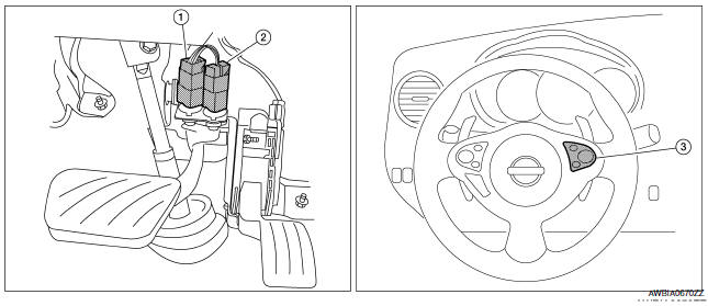
- Stop lamp switch
- ASCD brake switch
- ASCD steering switch
Component Description
Component Reference
- Accelerator pedal position sensor EC-467, "Description"
- Camshaft position sensor (PHASE) EC-300, "Description"
- Crankshaft position sensor (POS) EC-296, "Description"
- Engine coolant temperature sensor EC-201, "Description"
- Mass air flow sensor EC-183, "Description"
- Throttle position sensor EC-207, "Description"
- Power valve 1 and 2 EC-518, "Description"
- VIAS control solenoid valve 1 EC-442, "Description"
- VIAS control solenoid valve 2
 Intake valve timing control
System Diagram
System Description
INPUT/OUTPUT SIGNAL CHART
*: This signal is sent to the ECM via the CAN communication line
SYSTEM DESCRIPTION
This mechanism hydraulically controls c ...
 Fuel filler cap warning system
System Diagram
System Description
INPUT/OUTPUT SIGNAL CHART
Input
*: This signal is sent to the ECM via the CAN communication line.
Output
*: This signal is sent to the combination meter ...
Other materials:
ASCD indicator
Description
ASCD indicator lamp illuminates to indicate ASCD operation status. CRUISE is
integrated in combination
meter.
CRUISE illuminates when MAIN switch on ASCD steering switch is turned ON to
indicated that ASCD system
is ready for operation.
Refer to EC-68, "System Diagram ...
AMP on signal circuit
Description
When the audio system is turned on, a voltage signal is supplied from the AV
control unit to the BOSE speaker
amp. When this signal is received, the BOSE speaker amp. will turn on.
Diagnosis Procedure
1.CHECK AMP ON SIGNAL (BOSE SPEAKER AMP)
Turn audio system ON.
Check v ...
Removal and installation
STARTER MOTOR
Removal and Installation
REMOVAL
Remove the battery tray. Refer to PG-68, "Removal and Installation
(Battery Tray)".
Disconnect the battery cable (A) and starter harness connector.
Remove the starter bolts, then remove the starter
INSTALLATION
Installatio ...
Nissan Maxima Owners Manual
- Illustrated table of contents
- Safety-Seats, seat belts and supplemental restraint system
- Instruments and controls
- Pre-driving checks and adjustments
- Monitor, climate, audio, phone and voice recognition systems
- Starting and driving
- In case of emergency
- Appearance and care
- Do-it-yourself
- Maintenance and schedules
- Technical and consumer information
Nissan Maxima Service and Repair Manual

0.0074