Nissan Maxima Service and Repair Manual: Power supply and ground circuit
BCM
BCM : Diagnosis Procedure
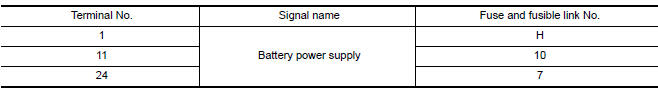
1. CHECK FUSE AND FUSIBLE LINK
Check if the following BCM fuses or fusible link are blown.
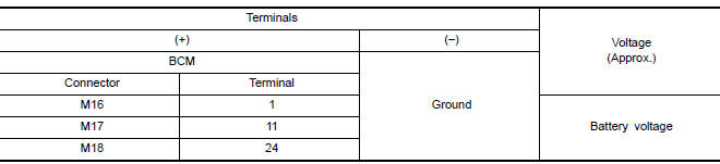
2. CHECK POWER SUPPLY CIRCUIT
- Turn ignition switch OFF.
- Disconnect BCM.
- Check voltage between BCM harness connector and ground.
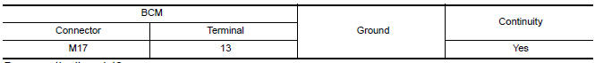
3. CHECK GROUND CIRCUIT
Check continuity between BCM harness connector and ground
BCM : Special Repair Requirement
1. REQUIRED WORK WHEN REPLACING BCM
Initialize control unit.

 Battery saver output/power supply circuit
Description
Provides the interior room lamp power supply. Also cuts the power supply when
the interior room lamp battery saver is activated.
Component Function Check
1.CHECK BATTERY SAVER OUTPUT/ ...
Other materials:
RearView Monitor system limitations
WARNING
Listed below are the system limitations for
RearView Monitor. Failure to operate the
vehicle in accordance with these system
limitations could result in serious injury or
death.
The system cannot completely eliminate
blind spots and may not show every
object.
Underneath the bu ...
Climate controlled seat switches (if so equipped)
The climate controlled seat warms up or cools
down the front seat by blowing warm or cool air
from under the surface of the seat. The climate
control switch is located on the center console.
The climate controlled seat can be operated as
follows:
1. Start the engine.
2. Turn the contr ...
Drive belt
VQ35DE engine
1. Crankshaft pulley
2. Drive belt automatic tensioner pulley
3. Generator pulley
4. Air conditioner compressor pulley
WARNING
Be sure the ignition switch is placed in the
OFF or LOCK position before servicing
drive belt. The engine could rotate
unexpectedly.
1. Visually ...
Nissan Maxima Owners Manual
- Illustrated table of contents
- Safety-Seats, seat belts and supplemental restraint system
- Instruments and controls
- Pre-driving checks and adjustments
- Monitor, climate, audio, phone and voice recognition systems
- Starting and driving
- In case of emergency
- Appearance and care
- Do-it-yourself
- Maintenance and schedules
- Technical and consumer information
Nissan Maxima Service and Repair Manual

0.0059