Nissan Maxima Service and Repair Manual: Battery saver output/power supply circuit
Description
Provides the interior room lamp power supply. Also cuts the power supply when the interior room lamp battery saver is activated.
Component Function Check
1.CHECK BATTERY SAVER OUTPUT/POWER SUPPLY FUNCTION
CONSULT
- Turn ignition switch ON.
- Turn each interior room lamp ON.
- Front room/map lamp assembly
- Personal lamps rear
- Foot lamps
- Front step lamps
- Rear step lamps
- Trunk room lamp
- Vanity mirror lamps
- Select "BATTERY SAVER" of BCM (BATTERY SAVER) active test item.
- While operating the test item, check that each interior room lamp turns ON/OFF.
OFF : Interior room lamp OFF
ON : Interior room lamp ON
Diagnosis Procedure
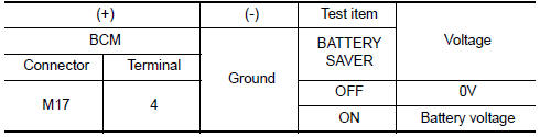
1.CHECK BATTERY SAVER OUTPUT/POWER SUPPLY OUTPUT
CONSULT
- Turn ignition switch ON.
- Select "BATTERY SAVER" of BCM (BATTERY SAVER) active test item.
- While operating the test item, check voltage between BCM connector M17 terminal 4 and ground.
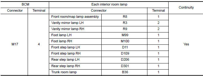
2.CHECK BATTERY SAVER OUTPUT/POWER SUPPLY OPEN CIRCUIT
- Turn ignition switch OFF.
- Disconnect the following connectors.
- BCM M17
- Front room/map lamp assembly
- Vanity mirror lamp LH
- Vanity mirror lamp RH
- Foot lamp LH
- Foot lamp RH
- Front step lamp LH
- Front step lamp RH
- Rear step lamp LH
- Rear step lamp RH
- Trunk room lamp
- Check continuity between BCM connector M17 terminal 4 and each interior room lamp connector.
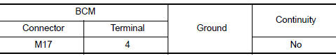
3.CHECK BATTERY SAVER OUTPUT/POWER SUPPLY SHORT CIRCUIT
Check continuity between BCM connector M17 terminal 4 and ground.
 Power supply and ground circuit
BCM
BCM : Diagnosis Procedure
1. CHECK FUSE AND FUSIBLE LINK
Check if the following BCM fuses or fusible link are blown.
2. CHECK POWER SUPPLY CIRCUIT
Turn ignition switch OFF.
Disconnec ...
 Interior room lamp control circuit
Description
Controls each interior room lamp (ground side) by PWM signal.
NOTE: PWM signal control period is
approximately 250 Hz (in the gradual brightening/dimming).
Component Function Check
...
Other materials:
P2122, P2123 APP sensor
Description
The accelerator pedal position sensor is installed on the upper end
of the accelerator pedal assembly. The sensor detects the accelerator
position and sends a signal to the ECM.
Accelerator pedal position sensor has two sensors. These sensors
are a kind of potentiometer which t ...
Instrument Panel
Vent
Headlight/fog light/turn signal switch
Supplemental front-impact air bag. Horn
Meters and gauges. Warning and indicator lights. Vehicle information
display
Paddle shifters (if so equipped)
Wiper and washer switch
Audio controls*. Navigation controls*
Hazard warning flash ...
P1225 TP sensor
Description
Electric throttle control actuator consists of throttle control motor,
throttle position sensor, etc. The throttle position sensor responds to
the throttle valve movement.
The throttle position sensor has two sensors. These sensors are a
kind of potentiometer which transfor ...
Nissan Maxima Owners Manual
- Illustrated table of contents
- Safety-Seats, seat belts and supplemental restraint system
- Instruments and controls
- Pre-driving checks and adjustments
- Monitor, climate, audio, phone and voice recognition systems
- Starting and driving
- In case of emergency
- Appearance and care
- Do-it-yourself
- Maintenance and schedules
- Technical and consumer information
Nissan Maxima Service and Repair Manual

0.006