Nissan Maxima Service and Repair Manual: Interior room lamp control circuit
Description
Controls each interior room lamp (ground side) by PWM signal.
NOTE: PWM signal control period is approximately 250 Hz (in the gradual brightening/dimming).
Component Function Check
CAUTION: Before performing the diagnosis, check that the following is normal.
- Battery saver output/power supply
- Front room/map lamp assembly bulbs
- Personal lamp rear bulbs
- Foot lamp bulbs
1.CHECK INTERIOR ROOM LAMP CONTROL FUNCTION
CONSULT
- Switch the front room/map lamp assembly to DOOR.
- Turn ignition switch ON.
- Select "INT LAMP" of BCM (INT LAMP) active test item.
- While operating the test item, check that each interior room lamp turns ON/OFF (gradual brightening/dimming).
ON : Interior room lamp gradual brightening
OFF : Interior room lamp
gradual dimming
Diagnosis Procedure
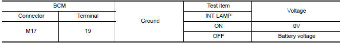
1.CHECK INTERIOR ROOM LAMP CONTROL OUTPUT
CONSULT
- Turn ignition switch ON.
- Select "INT LAMP" of BCM (INT LAMP) active test item.
- While operating the test item, check voltage between BCM connector M17 terminal 19 and ground.
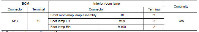
2.CHECK INTERIOR ROOM LAMP CONTROL OPEN CIRCUIT
- Turn ignition switch OFF.
- Disconnect BCM connector M17, front room/map lamp assembly and foot lamp connectors.
- Check continuity between BCM connector M17 terminal 19 and each interior room lamp connector.
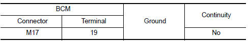
3.CHECK INTERIOR ROOM LAMP CONTROL SHORT CIRCUIT
- Turn ignition switch OFF.
- Disconnect BCM connector M17, front room/map lamp assembly and foot lamp connectors.
- Check continuity between BCM connector M17 terminal 19 and ground.
 Battery saver output/power supply circuit
Description
Provides the interior room lamp power supply. Also cuts the power supply when
the interior room lamp battery saver is activated.
Component Function Check
1.CHECK BATTERY SAVER OUTPUT/ ...
 Step lamp circuit
Description
Controls the step lamp (ground side) to turn the step lamp ON and OFF.
Component Function Check
CAUTION: Before performing the diagnosis,
check that the following is normal.
Batte ...
Other materials:
DLC branch line circuit
Diagnosis Procedure
1.CHECK CONNECTOR
Turn the ignition switch OFF.
Disconnect the battery cable from the negative terminal.
Check the terminals and connectors of the data link connector for
damage, bend and loose connection
(connector side and harness side).
2.CHECK HARNESS FOR OP ...
System description
COMPRESSOR CONTROL FUNCTION
Description
PRINCIPLE OF OPERATION
Compressor is not activated.
Functional circuit diagram
CAN (1): A/C switch signal
: Blower fan motor switch signal
CAN (2): A/C compressor request signal
Functional initial inspection chart
Fail-Safe
FAIL-SAFE FUNCTION ...
Active trace control
The Integrated Dynamics-control Module is an
electric control module that includes the following
functions:
Active Trace Control
Active Engine Brake
Active Ride Control
This system senses driving based on the driver's
steering and acceleration/braking patterns, and
controls brake pres ...
Nissan Maxima Owners Manual
- Illustrated table of contents
- Safety-Seats, seat belts and supplemental restraint system
- Instruments and controls
- Pre-driving checks and adjustments
- Monitor, climate, audio, phone and voice recognition systems
- Starting and driving
- In case of emergency
- Appearance and care
- Do-it-yourself
- Maintenance and schedules
- Technical and consumer information
Nissan Maxima Service and Repair Manual

0.0066