Nissan Maxima Service and Repair Manual: Step lamp circuit
Description
Controls the step lamp (ground side) to turn the step lamp ON and OFF.
Component Function Check
CAUTION: Before performing the diagnosis, check that the following is normal.
- Battery saver output/power supply
- Step lamp bulbs
1.CHECK STEP LAMP OPERATION
CONSULT
- Turn ignition switch ON.
- Select "STEP LAMP TEST" of BCM (INT LAMP) active test item.
- While operating the test item, check that step lamps turn ON/OFF.
ON : Step lamp ON
OFF : Step lamp OFF
Diagnosis Procedure
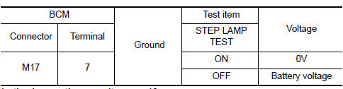
1.CHECK STEP LAMP OUTPUT
CONSULT
- Turn ignition switch ON.
- Select "STEP LAMP TEST" of BCM (INT LAMP) active test item.
- While operating the test item, check voltage between BCM connector M17 terminal 7 and ground.
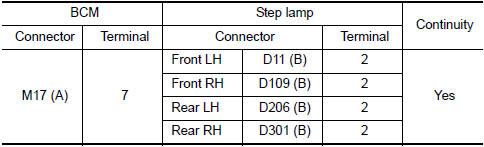
2.CHECK STEP LAMP OPEN CIRCUIT
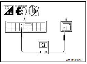
- Turn ignition switch OFF.
- Disconnect BCM connector M17 and step lamp connectors.
- Check continuity between BCM connector M17 (A) terminal 7 and step lamp connectors (B) terminal 2.
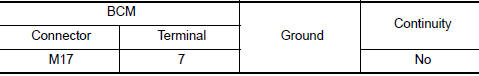
3.CHECK STEP LAMP SHORT CIRCUIT
- Turn ignition switch OFF.
- Disconnect BCM connector M17 and step lamp connectors.
- Check continuity between BCM connector M17 terminal 7 and ground.
 Interior room lamp control circuit
Description
Controls each interior room lamp (ground side) by PWM signal.
NOTE: PWM signal control period is
approximately 250 Hz (in the gradual brightening/dimming).
Component Function Check
...
 Trunk room lamp circuit
Description
Controls the trunk room lamp (ground side) to turn the trunk room lamp ON and
OFF.
Component Function Check
CAUTION: Before performing the diagnosis,
check that the following is nor ...
Other materials:
Hands-free phone system
System Diagram
System Description
Refer to the owner's manual for Bluetooth telephone system operating
instructions. NOTE: Cellular
telephones must have their wireless connection set up (paired) before using the
Bluetooth telephone system.
Bluetooth telephone system allows users who
hav ...
Rear view monitor system
System Diagram
System Description
When the shift selector is in the R position, the display unit shows a view
to the rear of the vehicle. Lines which
indicate the vehicle clearance and distances are also displayed.
Component Parts Location
Tweeter LH M51
Center speaker M130
...
Daytime running light system
System Diagram
System Description
The headlamp system for Canada vehicles is equipped with a daytime light
relay that activates the high beam headlamps at approximately half
illumination whenever the engine is running. If the parking brake is
depressed before the engine is started, the day ...
Nissan Maxima Owners Manual
- Illustrated table of contents
- Safety-Seats, seat belts and supplemental restraint system
- Instruments and controls
- Pre-driving checks and adjustments
- Monitor, climate, audio, phone and voice recognition systems
- Starting and driving
- In case of emergency
- Appearance and care
- Do-it-yourself
- Maintenance and schedules
- Technical and consumer information
Nissan Maxima Service and Repair Manual

0.009