Nissan Maxima Service and Repair Manual: Trunk room lamp circuit
Description
Controls the trunk room lamp (ground side) to turn the trunk room lamp ON and OFF.
Component Function Check
CAUTION: Before performing the diagnosis, check that the following is normal.
- Battery saver output/power supply
- Trunk room lamp bulb
1.CHECK TRUNK ROOM LAMP OPERATION
CONSULT
- Turn ignition switch ON.
- Select "LUGGAGE LAMP TEST" of BCM (INT LAMP) active test item.
- While operating the test item, check that trunk room lamp turns ON/OFF.
ON : Trunk room lamp ON
OFF : Trunk room lamp OFF
Diagnosis Procedure
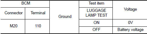
1.CHECK TRUNK ROOM LAMP OUTPUT
CONSULT
- Turn ignition switch ON.
- Select "LUGGAGE LAMP TEST" of BCM (INT LAMP) active test item.
- While operating the test item, check voltage between BCM connector M20 terminal 110 and ground.
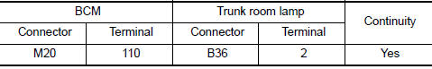
2.CHECK TRUNK ROOM LAMP OPEN CIRCUIT
- Turn ignition switch OFF.
- Disconnect BCM connector M20 and trunk room lamp connector.
- Check continuity between BCM connector M20 (A) terminal 110 and trunk room lamp connector B36 (B) terminal 2.
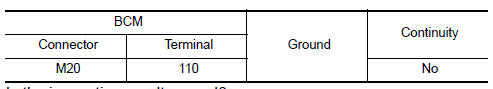
3.CHECK TRUNK ROOM LAMP SHORT CIRCUIT
- Turn ignition switch OFF.
- Disconnect BCM connector M20 and trunk room lamp connector.
- Check continuity between BCM connector M20 terminal 110 and ground
 Step lamp circuit
Description
Controls the step lamp (ground side) to turn the step lamp ON and OFF.
Component Function Check
CAUTION: Before performing the diagnosis,
check that the following is normal.
Batte ...
 Push-button ignition switch illumination circuit
Description
Provides the power supply and the ground to control the push-button ignition
switch illumination.
Component Function Check
1.CHECK PUSH-BUTTON IGNITION SWITCH ILLUMINATION OPERATION
...
Other materials:
Door locks/unlocks precaution
Do not push the door handle request switch
with the Intelligent Key held in your hand as
illustrated. The close distance to the door
handle will cause the Intelligent Key system
to have difficulty recognizing that the Intelligent
Key is outside the vehicle.
After locking with the ...
Chassis & body maintenance
Abbreviations: I = Inspect and correct or replace as necessary, R =
Replace,
NOTE:
Maintenance items with " " should be performed more frequently according
to "Maintenance under severe driving conditions".
(1) If towing a trailer, using a camper or a car-top carrier or driving on ro ...
BCM (body control module)
Reference Value
NOTE: The Signal Tech II Tool (J-50190) can
be used to perform the following functions. Refer to the Signal Tech II User
Guide for additional information.
Activate and display TPMS transmitter IDs
Display tire pressure reported by the TPMS transmitter
Read TPMS DTCs
Re ...
Nissan Maxima Owners Manual
- Illustrated table of contents
- Safety-Seats, seat belts and supplemental restraint system
- Instruments and controls
- Pre-driving checks and adjustments
- Monitor, climate, audio, phone and voice recognition systems
- Starting and driving
- In case of emergency
- Appearance and care
- Do-it-yourself
- Maintenance and schedules
- Technical and consumer information
Nissan Maxima Service and Repair Manual

0.0065