Nissan Maxima Service and Repair Manual: Steering wheel
Removal and Installation
REMOVAL
NOTE: When removing spiral cable, use tape so that the case and rotating part keep aligned. This will prevent neutral position alignment procedure during spiral cable installation.
- Set steering wheel to the straight-ahead position.
- Remove driver air bag module. Refer to SR-12, "Removal and Installation".
- Remove steering wheel lock nut after steering is locked.
- Remove steering wheel using Tool (A).
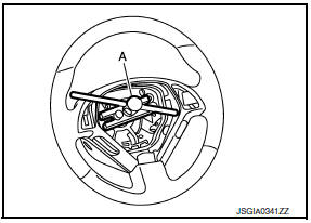
Tool number (A) : ST27180001 (J-25726-A)
INSTALLATION Installation is in the reverse order of removal.
CAUTION: Do not rotate spiral cable freely or excessively when the steering wheel is removed. Doing so may cause spiral cable damage.
NOTE:
- Check the spiral cable neutral position after replacing or rotating spiral cable. Refer to SR-15, "Removal and Installation".
- Tighten the steering wheel lock nut to specification.

 Tilt motor
Exploded View
Steering column assembly
Telescope motor
Telescope motor link bracket
Tilt motor
Tilt motor bolt cap
Removal and Installation
REMOVAL
Remove instrument lower pan ...
Other materials:
EBD
System Diagram
System Description
Electric Brake force Distribution functions as follows:
ABS actuator and electric unit (control unit) detects subtle
slippages between the front and rear wheels during
braking. Then it electronically controls the rear braking force (brake fluid
pr ...
Unlock sensor
Description
Detects door lock condition of driver door.
Component Function Check
1. CHECK FUNCTION
With CONSULT
Check unlock sensor UNLK SEN−DR in "Data Monitor" mode.
Diagnosis Procedure
1. CHECK UNLOCK SENSOR POWER SUPPLY
Check signal between BCM connector and ground with o ...
Removal and installation
COMPRESSOR
Removal and Installation for Compressor
REMOVAL
CAUTION: Before servicing, turn the ignition
switch off, disconnect both battery terminals and wait at least three
minutes.
Disconnect the battery negative and positive terminals. Refer to
PG-67, "Removal and Installation ( ...
Nissan Maxima Owners Manual
- Illustrated table of contents
- Safety-Seats, seat belts and supplemental restraint system
- Instruments and controls
- Pre-driving checks and adjustments
- Monitor, climate, audio, phone and voice recognition systems
- Starting and driving
- In case of emergency
- Appearance and care
- Do-it-yourself
- Maintenance and schedules
- Technical and consumer information
Nissan Maxima Service and Repair Manual

0.0061