Nissan Maxima Service and Repair Manual: CAN communication circuit
Diagnosis Procedure
1.CONNECTOR INSPECTION
- Turn the ignition switch OFF.
- Disconnect the battery cable from the negative terminal.
- Disconnect all the unit connectors on CAN communication system.
- Check terminals and connectors for damage, bend and loose connection.
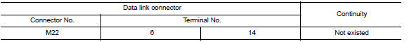
2.CHECK HARNESS CONTINUITY (SHORT CIRCUIT)
Check the continuity between the data link connector terminals.
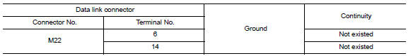
3.CHECK HARNESS CONTINUITY (SHORT CIRCUIT)
Check the continuity between the data link connector and the ground.
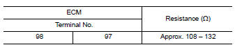
4.CHECK ECM AND IPDM E/R TERMINATION CIRCUIT
- Remove the ECM and the IPDM E/R.
- Check the resistance between the ECM terminals
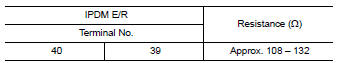
3. Check the resistance between the IPDM E/R terminals.
5.CHECK SYMPTOM
Connect all the connectors. Check if the symptoms described in the "Symptom (Results from interview with customer)" are reproduced.
Inspection result Reproduced>>GO TO 6.
Non-reproduced>>Start the diagnosis again. Follow the trouble diagnosis procedure when past error is detected.
6.CHECK UNIT REPRODUCTION
Perform the reproduction test as per the following procedure for each unit.
- Turn the ignition switch OFF.
- Disconnect the battery cable from the negative terminal.
- Disconnect one of the unit connectors of CAN communication system.
NOTE: ECM and IPDM E/R have a termination circuit. Check other units first.
- Connect the battery cable to the negative terminal. Check if the
symptoms described in the "Symptom
(Results from interview with customer)" are reproduced.
NOTE: Although unit-related error symptoms occur, do not confuse them with other symptoms.
Inspection result Reproduced>>Connect the connector. Check other units as per the above procedure.
Non-reproduced>>Replace the unit whose connector was disconnected.
 TCM branch line circuit
Diagnosis Procedure
1.CHECK CONNECTOR
Turn the ignition switch OFF.
Disconnect the battery cable from the negative terminal.
Check the following terminals and connectors for damage, bend and ...
 DTC/circuit diagnosis
MAIN LINE BETWEEN DLC AND HVAC CIRCUIT
Diagnosis Procedure
1.CHECK HARNESS CONTINUITY (OPEN CIRCUIT)
Turn the ignition switch OFF.
Disconnect the battery cable from the negative terminal.
Di ...
Other materials:
Symptom diagnosis
REFRIGERATION SYSTEM SYMPTOMS
WITH COLOR DISPLAY
WITH COLOR DISPLAY : Trouble Diagnoses for Abnormal Pressure
Whenever system′s high and/or low side pressure is abnormal, diagnose using a
manifold gauge. The marker above the gauge scale in the following tables
indicates the standard (us ...
Tel antenna
Removal and Installation
REMOVAL
Disconnect the battery negative terminal. Refer to PG-68, "Removal
and Installation (Battery Tray)".
Remove the rear parcel shelf finisher. Refer to INT-28, "Removal and
Installation".
Remove the Bluetooth antenna screw (A).
Detach the Bluetooth a ...
Hands-free phone system
System Diagram
System Description
Refer to the Owner's Manual for Bluetooth telephone system operating
instructions.
NOTE: Cellular telephones must have their
wireless connection set up (paired) before using the Bluetooth telephone
system.
Bluetooth telephone system allows users who have ...
Nissan Maxima Owners Manual
- Illustrated table of contents
- Safety-Seats, seat belts and supplemental restraint system
- Instruments and controls
- Pre-driving checks and adjustments
- Monitor, climate, audio, phone and voice recognition systems
- Starting and driving
- In case of emergency
- Appearance and care
- Do-it-yourself
- Maintenance and schedules
- Technical and consumer information
Nissan Maxima Service and Repair Manual

0.0073