Nissan Maxima Service and Repair Manual: TCM branch line circuit
Diagnosis Procedure
1.CHECK CONNECTOR
- Turn the ignition switch OFF.
- Disconnect the battery cable from the negative terminal.
- Check the following terminals and connectors for damage, bend and
loose connection (unit side and connector
side).
- TCM
- Harness connector F1
- Harness connector E3
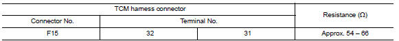
2.CHECK HARNESS FOR OPEN CIRCUIT
- Disconnect the connector of TCM.
- Check the resistance between the TCM harness connector terminals.
3.CHECK POWER SUPPLY AND GROUND CIRCUIT
Check the power supply and the ground circuit of the TCM. Refer to TM-126, "Wiring Diagram".
IPDM-E BRANCH LINE CIRCUIT
Diagnosis Procedure
1.CHECK CONNECTOR
- Turn the ignition switch OFF.
- Disconnect the battery cable from the negative terminal.
- Check the terminals and connectors of the IPDM E/R for damage, bend and loose connection (unit side and connector side).
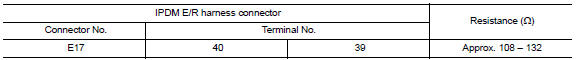
2.CHECK HARNESS FOR OPEN CIRCUIT
- Disconnect the connector of IPDM E/R.
- Check the resistance between the IPDM E/R harness connector terminals.
3.CHECK POWER SUPPLY AND GROUND CIRCUIT
Check the power supply and the ground circuit of the IPDM E/R. Refer to PCS-18, "Diagnosis Procedure".
 ABS branch line circuit
Diagnosis Procedure
1.CHECK CONNECTOR
Turn the ignition switch OFF.
Disconnect the battery cable from the negative terminal.
Check the terminals and connectors of the ABS actuator and
elec ...
 CAN communication circuit
Diagnosis Procedure
1.CONNECTOR INSPECTION
Turn the ignition switch OFF.
Disconnect the battery cable from the negative terminal.
Disconnect all the unit connectors on CAN communication syste ...
Other materials:
Audio system
System Diagram
System Description
AUDIO SYSTEM
The audio system consists of the following components
AV control unit
Display unit
BOSE speaker amp.
Window antenna
Steering wheel audio control switches
A/C and AV switch assembly
Front door speakers
Tweeters
Center speaker
...
Vehicle information display warnings and indicators
No Key Detected
Key ID Incorrect
Key Battery Low
I-Key System Error: See Owner's Manual
Shift to Park
Push brake and start switch to drive
Engine start operation for Intelligent Key system
(if I-Key battery level is low)
Release Parking Brake
Low Fuel
Low Washer Fluid
Ti ...
Precaution
Precaution for Supplemental Restraint System (SRS) "AIR BAG" and
"SEAT BELT PRE-TENSIONER"
The Supplemental Restraint System such as "AIR BAG" and "SEAT BELT
PRE-TENSIONER", used along with a front seat belt, helps to reduce the risk
or severity of injury to the driver and front passenger for ...
Nissan Maxima Owners Manual
- Illustrated table of contents
- Safety-Seats, seat belts and supplemental restraint system
- Instruments and controls
- Pre-driving checks and adjustments
- Monitor, climate, audio, phone and voice recognition systems
- Starting and driving
- In case of emergency
- Appearance and care
- Do-it-yourself
- Maintenance and schedules
- Technical and consumer information
Nissan Maxima Service and Repair Manual

0.0085