Nissan Maxima Service and Repair Manual: ABS branch line circuit
Diagnosis Procedure
1.CHECK CONNECTOR
- Turn the ignition switch OFF.
- Disconnect the battery cable from the negative terminal.
- Check the terminals and connectors of the ABS actuator and electric unit (control unit) for damage, bend and loose connection (unit side and connector side).
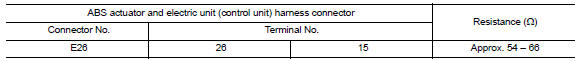
2.CHECK HARNESS FOR OPEN CIRCUIT
- Disconnect the connector of ABS actuator and electric unit (control unit).
- Check the resistance between the ABS actuator and electric unit (control unit) harness connector terminals.
3.CHECK POWER SUPPLY AND GROUND CIRCUIT
Check the power supply and the ground circuit of the ABS actuator and electric unit (control unit). Refer to BRC-83, "Wiring Diagram".
 A-bag branch line circuit
Diagnosis Procedure
WARNING:
Always observe the following items for preventing accidental
activation.
Before servicing, turn ignition switch OFF, disconnect battery negative
terminal, and wa ...
 TCM branch line circuit
Diagnosis Procedure
1.CHECK CONNECTOR
Turn the ignition switch OFF.
Disconnect the battery cable from the negative terminal.
Check the following terminals and connectors for damage, bend and ...
Other materials:
Washer motor circuit
Diagnosis Procedure
1. CHECK FRONT WASHER MOTOR FUSE
Turn the ignition switch OFF.
Check that the following fuse is not blown.
2. CHECK FRONT WASHER MOTOR POWER SUPPLY
Disconnect front washer motor.
Turn ignition switch ON.
Check voltage between front washer motor harness conne ...
Microphone signal circuit
Description
Voice signals are transmitted from the microphone to the Bluetooth control
unit using the microphone signal circuits.
Diagnosis Procedure
1.CHECK HARNESS BETWEEN BLUETOOTH CONTROL UNIT AND MICROPHONE
Turn ignition switch OFF.
Disconnect Bluetooth control unit connector and ...
Front grille
Removal and Installation
Core support cover
Front grille Pawl
REMOVAL
Remove the core support cover clips, then remove core support
cover.
Release the front air guide clips, then remove front air guide.
Release the front grille pawls from behind and push outward, then
r ...
Nissan Maxima Owners Manual
- Illustrated table of contents
- Safety-Seats, seat belts and supplemental restraint system
- Instruments and controls
- Pre-driving checks and adjustments
- Monitor, climate, audio, phone and voice recognition systems
- Starting and driving
- In case of emergency
- Appearance and care
- Do-it-yourself
- Maintenance and schedules
- Technical and consumer information
Nissan Maxima Service and Repair Manual

0.0074