Nissan Maxima Service and Repair Manual: Replacement operations
Description
This section is prepared for technicians who have attained a high level of skill and experience in repairing collision- damaged vehicles and also use modern service tools and equipment. Persons unfamiliar with body repair techniques should not attempt to repair collision-damaged vehicles by using this section.
Technicians are also encouraged to read Body Repair Manual (Fundamentals) in order to ensure that the original functions and quality of the vehicle can be maintained. The Body Repair Manual (Fundamentals) contains additional information, including cautions and warnings, that are not including in this manual. Technicians should refer to both manuals to ensure proper repairs.
Please note that this information is prepared for worldwide usage, and as such, certain procedures might not apply in some regions or countries.
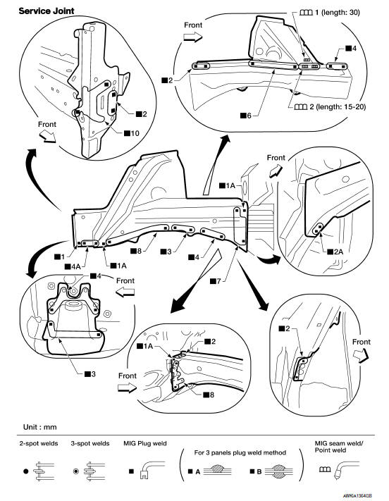
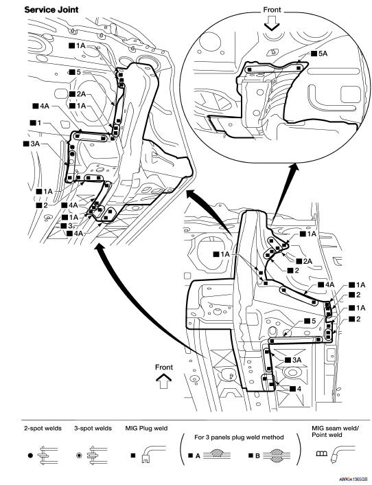
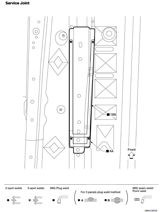
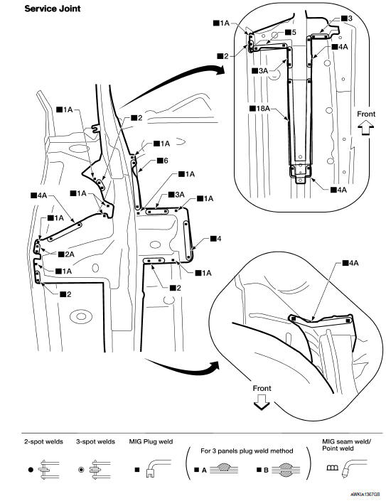
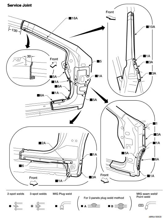
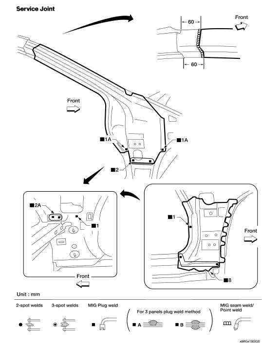
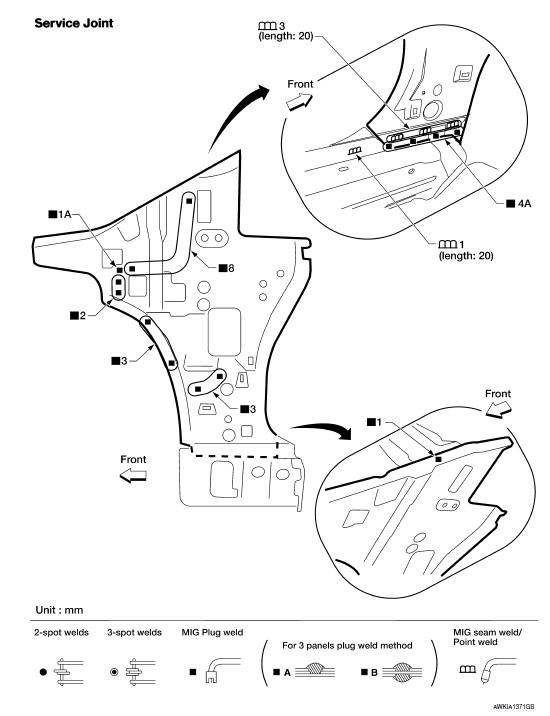
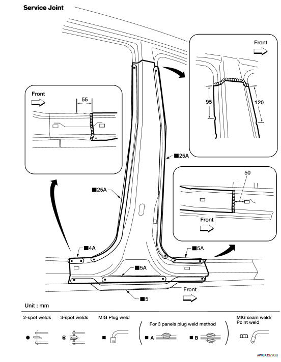
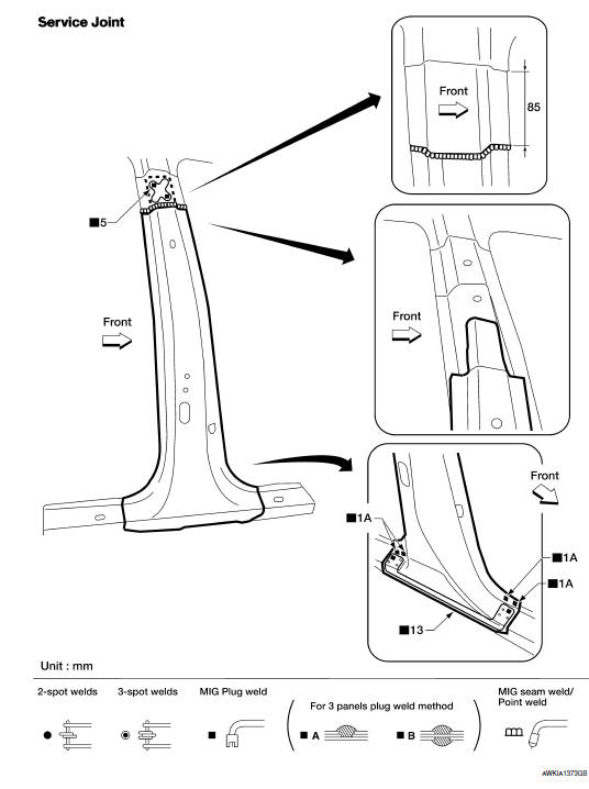
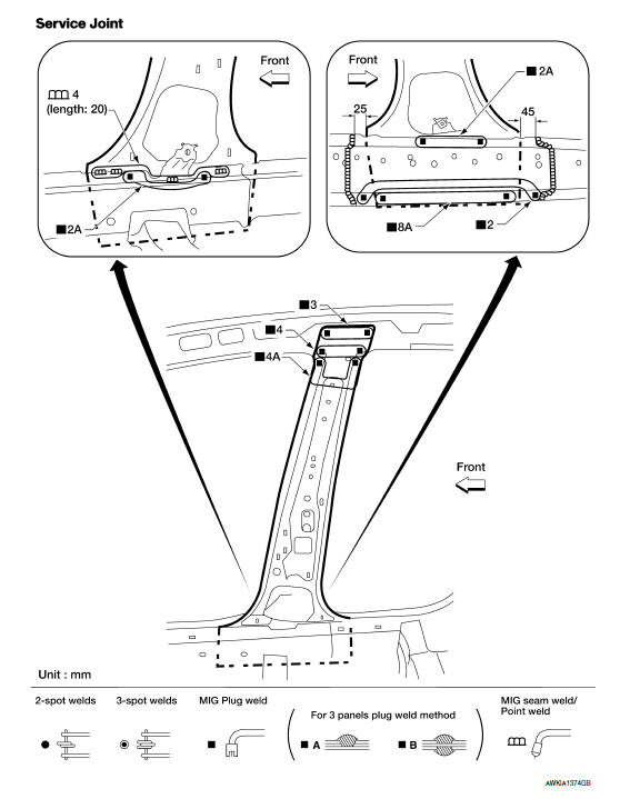
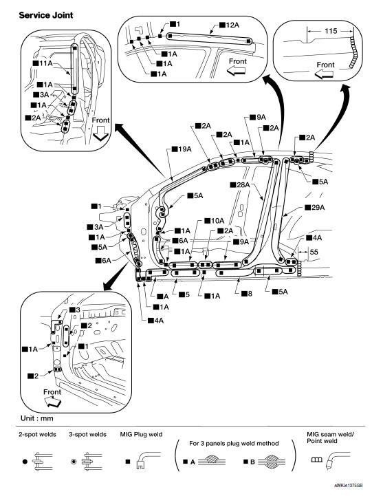
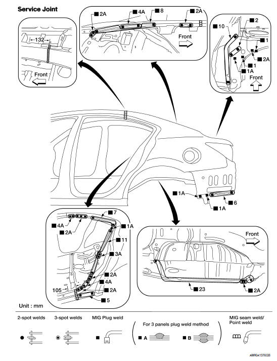
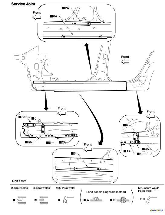
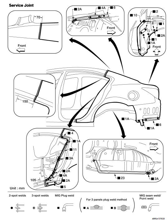
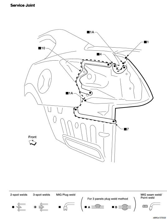
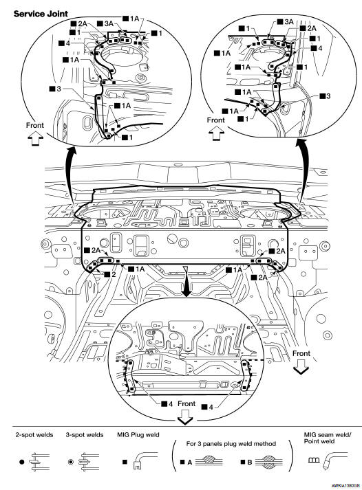
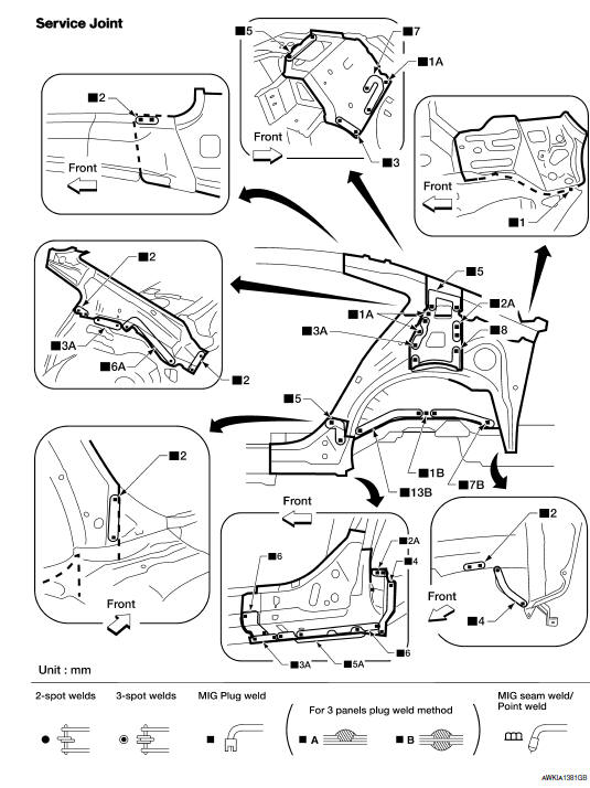
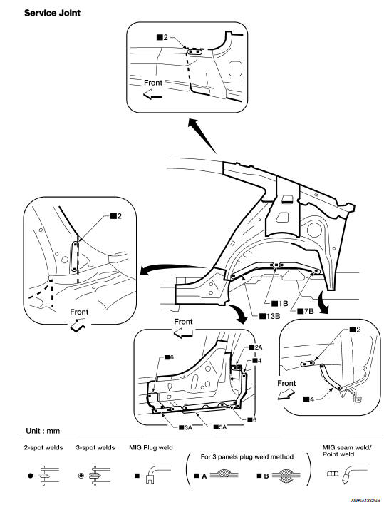
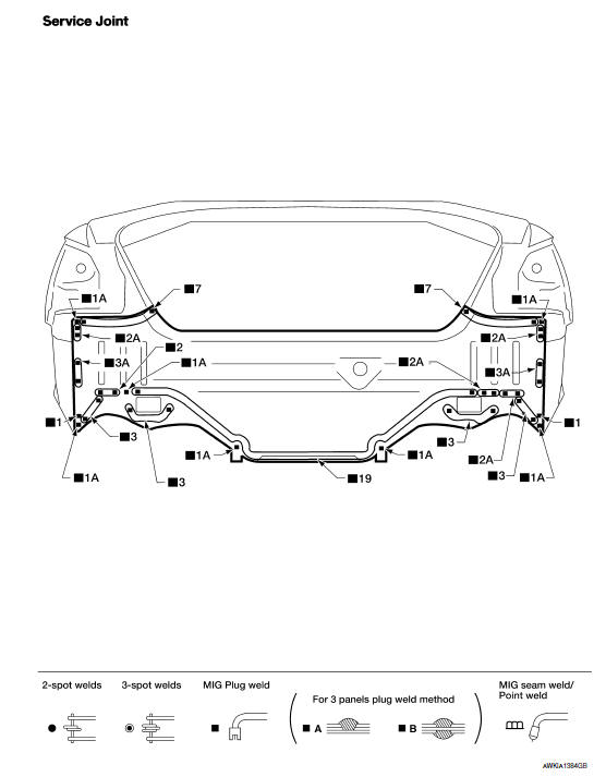
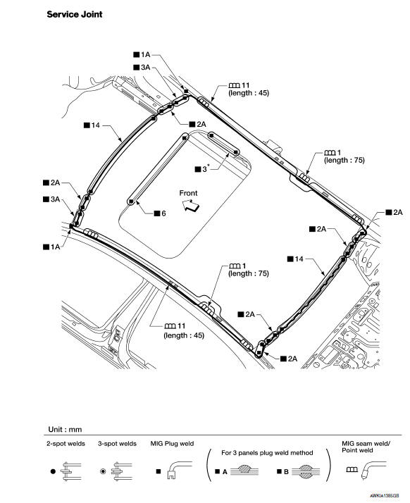
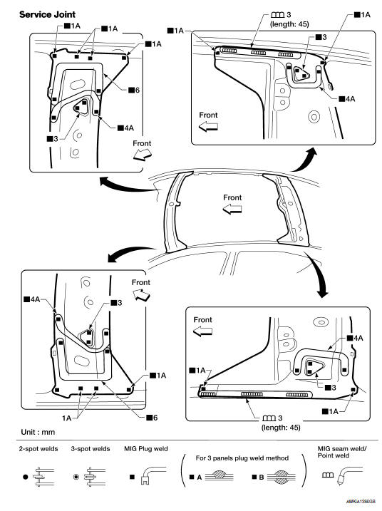
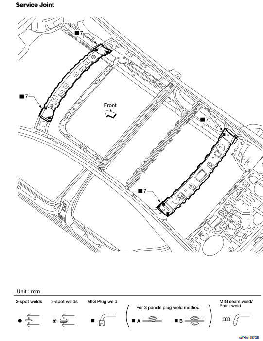
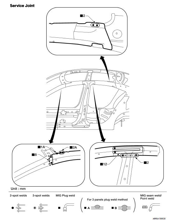
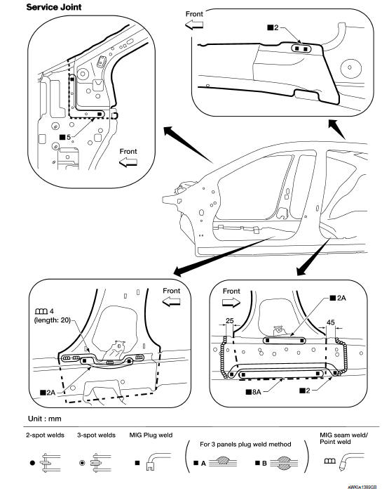
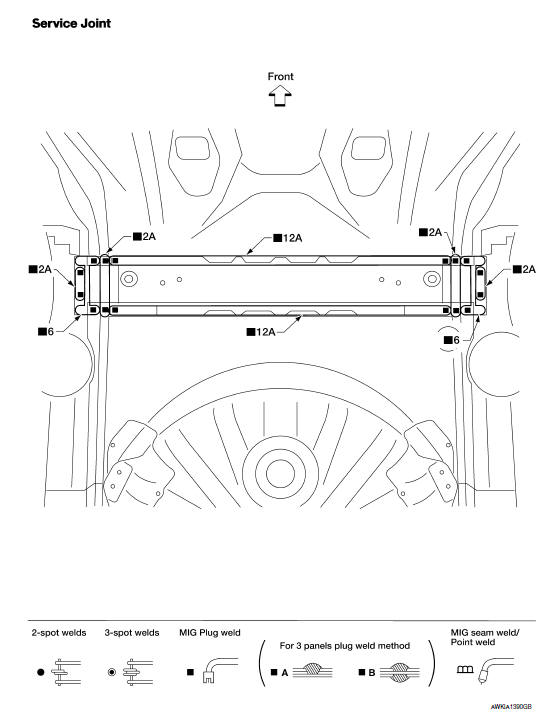
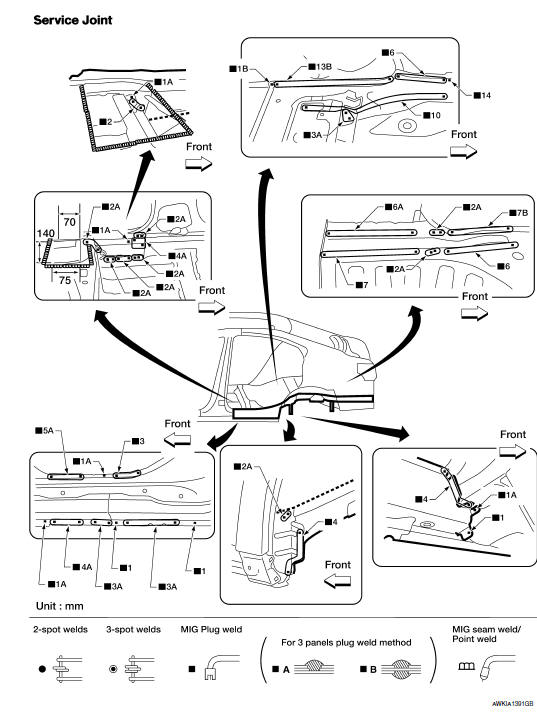
The symbols used in this section for cutting and welding / brazing operations are shown below.
- Front pillar butt joint can be determined anywhere within shaded area as shown in the figure. The best location for the butt joint is at position A due to the construction of the vehicle. Refer to the front pillar section.
- Determine cutting position and record distance from the locating indent. Use this distance when cutting the service part. Cut outer front pillar over 60 mm above inner front pillar cut position.
- Prepare a cutting jig to make outer pillar easier to cut. Also, this will permit service part to be accurately cut at joint position.
- An example of cutting operation using a cutting jig is as follows.
- Mark cutting lines.
- Cut position of outer pillar
- Cut position of inner pillar
- Align cutting line with notch on jig. Clamp jig to pillar.
- Cut outer pillar along groove of jig. (At position A)
- Remove jig and cut remaining portions.
- Cut inner pillar at position B in same manner.
FOAM REPAIR
During factory assembly, foam insulators are installed in certain body panels and locations around the vehicle.
Use the following procedure(s) to replace any factory-installed foam insulators.
Urethane Foam Applications Use commercially available spray for sealant (foam material) repair of material used on vehicle. Read instructions on product for fill procedures.
Fill Procedures
- Fill procedures after installation service part.
- Remove foam material remaining on vehicle side.
- Clean area in which foam was removed.
- Install service part.
- Insert nozzle into hole near fill area and fill foam material or fill in enough to close gap with service part
- Fill procedures before installation service part
- Remove foam material remaining on vehicle side.
- Clean area in which foam material on wheelhouse outer side was
removed.
NOTE: Fill in enough to close gap with service part while avoiding flange area. - Install service part.
NOTE: Refer to label for information on working times.
- Body side outer
- Body side insulation (foam) upper front pillar
- Body side insulation (foam) front pillar
- Roof panel assembly
- Roof panel insulation (foam) front roof rail (standard roof)
- Body side insulation (foam) rear pillar
- Body side insulation (foam) lower rear pillar
- Body side insulation strip front pillar lower reinforcement
- Body side insulation strip, center pillar reinforcement
NOTE:
Views F & G are shown with the body side outer removed.
Hoodledge
Replacement parts
- Front suspension spring support
- Hoodledge reinforcement
- Hoodledge lower assembly
- Upper radiator core support
Front Side Member (Partial Replacement)
Work after the hoodledge has been removed.
Replacement parts
- Front side member
- Closing plate assembly
- Radiator core side support
- Front suspension member weld nut plate
Work after front side member and closing plate assembly have been removed.
Replacement parts
- Front side member extension
Shown with front side member extension removed.
Replacement parts
- Front side member center extension
Front Side Member Assembly
Work after hoodledge has been removed.
Replacement parts
- Front side member assembly
Front Pillar
OUTER
Work after the upper hoodledge has been removed
Replacement parts
- Front pillar section of front body side outer
REINFORCEMENT
Work after front pillar section of the front body side outer has been removed.
Replacement parts
- Front pillar upper hinge brace
- Front pillar lower hinge brace
INNER
Work after front pillar upper hinge brace has been removed.

Replacement parts
- Front pillar inner reinforcement (partial)
Dash Side
Work after the front pillar portion of body side inner reinforcement and the front pillar lower hinge brace have been removed.
Replacement parts
- Dash side
Center Pillar
OUTER
Replacement parts
- Center pillar portion of front body side outer
REINFORCEMENT
Work after center pillar portion of front body side outer has been removed.
Replacement parts
- Center pillar reinforcement
INNER
Work after center pillar reinforcement has been removed
Replacement parts
- Center pillar inner reinforcement
Front Body Side Outer
Work after hoodledge reinforcement and front roof rail have been removed
Replacement parts
- Front body side outer
Rear Body Side Outer
Work after the tail lamp housing base and rear roof rail have been removed.
Replacement parts
- Rear body side outer
Outer Sill Reinforcement
Work after the front pillar lower hinge brace and the center pillar reinforcement have been removed.
Replacement parts
- Outer sill reinforcement
Rear Fender
Work with tail lamp housing base removed.
Replacement parts
- Rear fender
Tail Lamp Housing Base
Work after rear panel assembly has been removed.
Replacement parts
- Tail lamp housing base
Parcel Shelf
Replacement part
- Parcel shelf assembly
Rear Wheel Housing
Work after the rear body side outer and the parcel shelf have been removed.
Replacement parts
- Rear wheel housing assembly
- Rear pillar inner reinforcement
- Parcel shelf side
- Rear seatback side support
- Sill outer reinforcement rear
- Rear pillar inner
Rear Body Side Inner Assembly
Work after rear body side outer and parcel shelf have been removed.
Replacement parts
- Rear body side inner assembly
Rear Floor Rear
Work after rear panel assembly has been removed.
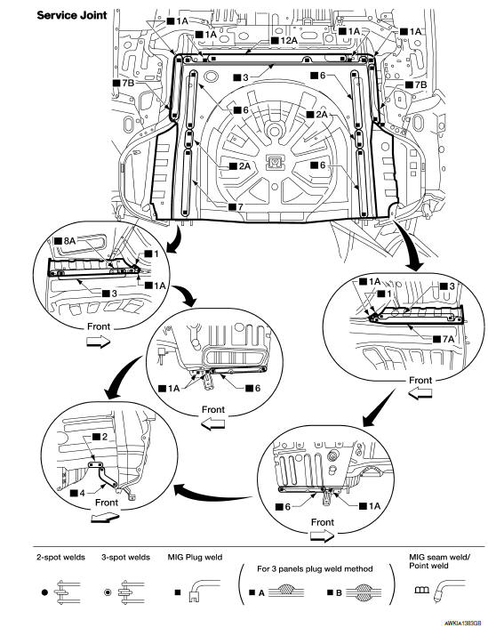
Replacement parts
- Rear floor rear
- Rear floor rear (RH)
- Rear floor rear (LH)
Rear Panel Assembly
Replacement parts
- Rear panel assembly
Roof
Replacement parts
- Roof panel, single panel sunroof
Roof Rails, Dual Panel Sunroof
Replacement parts
- Front roof rail
- Rear roof rail
Roof Rails, Single Panel Sunroof
Work after the roof has been removed.
Replacement parts
- Front roof rail (sunroof)
- Rear roof rail (sunroof)
Roof Side Rail
Work after the front and rear body side outer have been removed.
Replacement parts
- Roof side rail
Body Side Inner
Work after the roof side rail and the center pillar reinforcement have been removed.
Replacement parts
- Body side inner
Rear Center Crossmember
Replacement parts
- Rear center crossmember
Rear Side Member
Work after rear panel assembly and rear center crossmember have been removed
Replacement parts
- Rear side member assembly
 Precautions in repairing high strength steel
High Strength Steel (HSS)
High strength steel is used for body panels in order to reduce vehicle
weight.
Accordingly, precautions in repairing automotive bodies made of high strength
steel are ...
 Driver controls
...
Other materials:
Interior trunk lid release
WARNING
Closely supervise children when they are
around cars to prevent them from playing
and becoming locked in the trunk where
they could be seriously injured. Keep the
car locked, with the rear seatback and
trunk lid securely latched when not in use,
and prevent children's access to ca ...
Diagnosis and repair workflow
WorkFlow
DETAILED FLOW
1.OBTAIN INFORMATION ABOUT SYMPTOM
Interview the customer to obtain the malfunction information (conditions and
environment when the malfunction occurred) as much as possible when the
customer brings the vehicle in.
2.REPRODUCE THE MALFUNCTION INFORMATION
Check the ma ...
Audio unit
Removal and Installation
Audio unit brackets (LH/RH)
A/C auto amp.
Cluster lid C lower
Audio unit Clip
Pawl
REMOVAL
Disconnect the battery negative terminal. Refer to PG-67, "Removal
and Installation (Battery)".
Remove the cluster lid D. Refer to IP-11, "Removal and ...
Nissan Maxima Owners Manual
- Illustrated table of contents
- Safety-Seats, seat belts and supplemental restraint system
- Instruments and controls
- Pre-driving checks and adjustments
- Monitor, climate, audio, phone and voice recognition systems
- Starting and driving
- In case of emergency
- Appearance and care
- Do-it-yourself
- Maintenance and schedules
- Technical and consumer information
Nissan Maxima Service and Repair Manual

0.006